Technical Report on
the Titac
Ilmenite Exploration Project,
Minnesota, USA
Report Prepared for
Cardero Resource Corp.
Report Prepared by  SRK Consulting (Canada)
Inc. |
| 2CC031.004 – Cardero Resources | |
| Titac Project NI 43-101 | Page i |
Technical Report on the Titac Ilmenite
Exploration Project, Minnesota, USA
Cardero Resource Corp.
Suite 2300 – 1177 West Hastings Street
Vancouver,
BC,V6E 2K3
website: www.cardero.com
Tel: +1.604.408.7488
Fax: +1.604.408.7499
SRK Consulting (Canada) Inc.
Suite 2200 – 1066 West
Hastings Street
Vancouver, BC, V6E 3X2
e-mail: vancouver@srk.com
website: www.srk.com
Tel:
+1.604.681.4196
Fax: + 1.604.687.5532
SRK Project Number 2CC031.004
| Effective date: | January 19, 2012 |
| Report date: | January 27, 2012 |
Authored by:
|
||
| Darrell Farrow, P.Geo. | Mike Johnson, P.Geo. | |
| Associate Consultant (Geology) | Senior Consultant (Geology) | |
Peer Reviewed by:
|
||
| Wayne Barnett, Pr.Sci.Nat | ||
| Principle Consultant (Geology) | ||
| ____________________ | ||
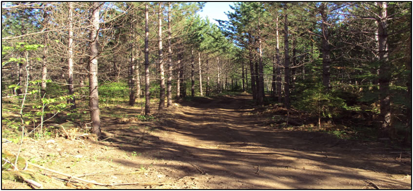
| Cover: Photo of drill support road at Titac (source Cardero) |
| DJF_MJ/WB | Titac-NI43-101Rpt (4).docx | January 27, 2012 |
| 2CC031.004 – Cardero Resources | |
| Titac Project NI 43-101 | Page 1 |
Important Notice
This report was prepared as a National Instrument 43-101 Technical Report for Cardero Resources Corp. (“Cardero” or the “Company”) by SRK Consulting (Canada) Inc. (“SRK”). The quality of information, conclusions, and estimates contained herein is consistent with the level of effort involved in SRK’s services, based on: i) information available at the time of preparation, ii) data supplied by outside sources, and iii) the assumptions, conditions, and qualifications set forth in this report. This report is intended for use by Cardero, subject to the terms and conditions of its contract with SRK and relevant securities legislation. The contract permits Cardero to file this report as a Technical Report with Canadian securities regulatory authorities pursuant to National Instrument 43-101(“NI 43-101”), Standards of Disclosure for Mineral Projects.
| DJF_MJ/WB | Titac-NI43-101Rpt (4).docx | January 27, 2012 |
| 2CC031.004 – Cardero Resources | |
| Titac Project NI 43-101 | Page 2 |
Executive Summary
This technical report documents the Mineral Resource estimate for the Titac Project (“the Project”). It was prepared following the guidelines of the Canadian Securities Administrators National Instrument 43-101 (“NI 43-101”) and Form 43-101F1, and in conformity with generally accepted CIM “Estimation of Mineral Resources and Mineral Reserves Best Practice Guidelines”. This report has been written by SRK Consulting (Canada) Inc. (“SRK”) on behalf of Cardero Resources Corp. (“Cardero” or the “Company”).
Property Description and Location
The land making up the Project (“Project Area”) is located in northeastern Minnesota in St. Louis County, Township 55N, Range 14W, Section 34, and Township 54N, Range 14W, Section 3. The property is approximately centered at: (Coordinate system: Universal Trans Mercator, Zone 15 North, North American 1983 Datum) 568000 m East, 5228000 m North.
The Project Area interests are held by Cardero Iron Ore (USA) Inc. (“CIOUS”), a wholly owned indirect subsidiary of Cardero, and work on the property is carried on through Cardero Iron Ore Management (USA) Inc., an indirectly wholly owned subsidiary of Cardero. Cardero holds a 100% leasehold interest in the Project Area under a mining lease dated July 1, 2009. The lease is for an initial term of 20 years, subject to extension for up to 20 additional years, and requires annual rental payments until commercial production and thereafter production royalty payments (minimum $200,000/year).
CIOUS has all required licenses, permits and registrations in place to carry out exploration and resource definition drilling. Additional permits will be required in the future to advance to the next stage.
Accessibility, Climate, Local Resources, Infrastructure and Physiography
Topographic relief on the Titac property is generally low, and the surface is flat-laying. Elevations range between 470 m and 490 m above mean sea level. The ground cover is a mixture of Palustrine, forested wetlands (Cowardin classification system), and higher dry forested ground. Overburden, consisting of glacial till, is present and the depth to bedrock is approximately 20 to 30 m (“m”) from surface.
Accessibility is excellent, with the Project Area located along a paved county highway.
The climate in northeastern Minnesota is mid-continental. Winter conditions usually begin in mid-December and last until mid-March, with frozen ground beginning in late-December to early-January. The spring thaw usually begins in mid-March to late-April, with stable, dry spring-summer-fall conditions occurring from late-April to mid-December.
The population of Aurora, Minnesota (the nearest major population centre) is approximately 1,850, and the nearby city of Hoyt Lakes (5 miles east of Aurora), Minnesota has a population of approximately 2,000 people.
The infrastructure in northeastern Minnesota related to mining activities is excellent, with low cost electricity, railroads, paved state and county highways, international shipping ports, mining professionals, mining vendors, and trained labor all readily available. International shipping ports are located along the north shore of Lake Superior, including Duluth/Superior, Silver Bay, Taconite Harbor, and Two Harbors, with linked rail systems to all.
| DJF_MJ/WB | Titac-NI43-101Rpt (4).docx | January 27, 2012 |
| 2CC031.004 – Cardero Resources | |
| Titac Project NI 43-101 | Page 3 |
History
Exploration of the Project Area, historically known as Section 34, has been limited, though several exploratory bore holes and geophysical surveys have been completed. Six holes were drilled historically (by United States Steel Corp), and Cardero completed 30 holes in 2010 and 2 holes in 2011. A ground magnetic survey was conducted in the mid-1960s by United States Steel Corp. A small amount of metallurgical testwork was completed by United States Steel Corp. in 1971.
Geological Setting and Mineralization
The Project Area is located within the Superior Province of the Canadian Shield, and is underlain by intrusive rocks generated during the formation of the Midcontinent Rift. Mineralization is hosted by Oxide-bearing Ultramafic Intrusions (“OUIs”) that intruded into layered series intrusions of the Duluth Complex. OUIs are dominantly composed of coarse-grained to pegmatitic pyroxenite, peridotite, and dunite that contain approximately 15-40% titanium-iron oxide mineralization. Typically, zones of massive and semi-massive oxide are also present throughout the stratigraphy. Locally, some OUIs also contain abundant copper-nickel sulfide mineralization. Most OUIs occur along the western margin of the southern portion of the Duluth Complex, and display numerous shapes (sheet-, funnel, dike- and pipe-like geometries), and inclinations (flat-lying, moderately-dipping, and sub-vertical). The Titac OUIs are geologically interpreted to be late-stage intrusions that cut early Duluth Complex stratigraphy, and are associated with magmatism generated by the 1.1 billion year old Midcontinent Rift system.
The Titac OUls contain disseminated, semi-massive, and massive titanium-iron oxide mineralization, dominantly ilmenite (TiFeO3) and magnetite and titaniferous magnetite (Fe3O4, Fe2TiO4). The Project Area contains at least two mineralized OUIs (Titac North and Titac South). Titac North is at least 450 m thick (open at depth) and has a vertical pipe-like geometry. Titac South is at least 490 m thick, and also has a pipe-like geometry.
Exploration and Drilling
Exploration of the Project Area by CIOUS began in 2010. Reinterpretation of the ground magnetic survey conducted by USSC confirmed the presence of multiple titaniferous-iron oxide-bearing intrusions at the Project Area including two large intrusions referred to as Titac North and Titac South. No bedrock is exposed on the Project Area with the result that bedrock mapping has not been undertaken.
Drilling at the Project Area is complex because of the stratigraphy of the Titac intrusions.
During 2010 and 2011, a total of 11,034.4 m were completed for 32 drill-holes, 8 (2685.3 m) of which were drilled at Titac North and 24 (8349.1 m) at Titac South. The drilling confirmed titanium-iron-oxide mineralization at the Project Area and determined that the Titac property contains at least two intrusions with large zones of titanium-iron-oxide mineralization (Titac North and Titac South). All assay results from the 2010 and 2011 drilling campaigns have been received and are included in this report.
| DJF_MJ/WB | Titac-NI43-101Rpt (4).docx | January 27, 2012 |
| 2CC031.004 – Cardero Resources | |
| Titac Project NI 43-101 | Page 4 |
Sample Preparation, Analyses and Security
Cardero has utilized a thorough and robust procedure for sampling, sample preparation, analysis and security.
Procedures for core handling, logging, sampling, and sample shipping were well thought out and well implemented. Analysis was completed by ALS, one of the largest commercial laboratories in the world. A robust program of quality assurance and quality control samples was implemented and met or exceeded industry standard procedures. Sample security and chain of custody documentation was maintained throughout the process and was thoroughly reviewed by SRK.
Data Verifications
Exploration data verification for the Project Area has included a site visit by SRK, enforced database structures, analytical quality assurance and quality control samples, independent sampling and assay checking.
SRK’s Wayne Barnett, Pri. Sci. Nat. visited the site in July 2009 and Mike Johnson, P. Geo, visited the site in March 2010. During these site visits, SRK verified drill hole locations, drilling, logging and sampling procedures, security and documentation. SRK also collected independent sampling during these site visits and confirmed the TiO2 and Fe2O3 values for two Titac samples.
Cardero utilized an onsite database which validated the data entry process as it was being completed and reduced clerical errors. In addition, Cardero’s head office checked the data upon import into their main exploration database in order to minimize data errors.
SRK verified 100% of the assay database by downloading these records directly from the commercial laboratory and checking them against the Mineral Resource database.
Cardero completed QA/QC sampling (blanks, standards, duplicates) totalling 1075 samples, equal to 22% of the total samples. SRK has reviewed the QA/QC sample insertion rate and results and found that they indicate that the analytical data should be reliable. However, analytical standards selection and certain standard results should be more carefully scrutinized for future programs.
Mineral Processing and Metallurgical Testing
Metallurgical test work (Davies Tube tests) was completed on two samples from one of the historical drill holes (26002) on the Project Area in 1972.
The historic metallurgical test work indicates a relatively simple processing flow sheet. It would include crushing the material to a selected size and processing the ore by density and then by magnetic properties. The density separation would remove the silicates from the much more dense oxides. The oxides would then be split into a non-magnetic / paramagnetic fraction as well as a magnetic fraction. Magnetite would partition into the magnetic fraction, while the ilmenite would partition into the non-magnetic / paramagnetic fraction. The magnetic fraction could be further upgraded to recover some ilmenite that would partition into that fraction. The ilmenite concentrate could then be sold to an external processing site, or could be processed at a newly created process facility as part of a further beneficiation/added value processing project; however, a potential upgrading facility would have very significant capital costs.
Cardero has completed very limited metallurgical testing at this stage. Recent work includes only Davies Tube tests, used to determine the proportion of magnetic iron commonly associated with magnetite. Significant further metallurgical work is required for the Project if further economic analysis is contemplated.
| DJF_MJ/WB | Titac-NI43-101Rpt (4).docx | January 27, 2012 |
| 2CC031.004 – Cardero Resources | |
| Titac Project NI 43-101 | Page 5 |
Mineral Resource Estimates
In July 2009, SRK was retained by Cardero to complete a Mineral Resource for the Titac OUI deposits, as well as update the technical report for the project.
SRK utilized Gemcom’s Gems version 6.3.1 to complete the Mineral Resource estimation. A comprehensive and validated drill hole database was utilized to complete the analysis. The database includes 32 drill holes, 8 of which were drilled in Titac North and 24 of which were drilled in Titac South. Drilling in Titac North was insufficient for the delineation of mineralized domains and resource estimation. The Mineral Resource presented here only includes Titac South. The estimation process utilized 2837 samples out of the databases 3929 samples for Titac South. A total of 855 specific gravity measurements were utilized to estimate bulk densities.
Three geological domains were modelled for the estimation process. The domains were defined by peridotite or pyroxenite dominated oxide bearing ultramafic rocks. A marginal zone of mixed perdidotite, pyroxenite and country rock was also modelled.
The Titac South resources were estimated using GemsTM (a Gemcom software product) block modeling software in multiple passes in 10 x 10 x 10 m blocks. Grade estimates were based on 1.8 m composited samples. Capping of TiO2 and Fe2O3 assays was not applied in any of the three domains. Ordinary kriging was used to estimate TiO2 and Fe2O3. Inverse distance squared was used to estimate the specific gravity data. Mineral resources were classified in accordance with definitions provided by the Canadian Institute of Mining (“CIM”) as stipulated in NI43-101. All interpolated blocks were classified as Inferred Mineral Resource.
In order to quantify the Mineral Resources requirement of “reasonable prospects of economic extraction”, the block model was subjected to conceptual mining limits using an open pit optimization program. The process uses reasonable mining and processing parameters to define a conceptual pit within which the material with reasonable economic prospects should be contained. For the Titac Project optimization runs, it was assumed that all TiO2 is contained in the mineral Ilmenite and no value was associated with the Fe2O3 material in order to avoid double counting of the value associated with iron. Historic metallurgical data indicates that a very high percentage of the TiO2 is contained within ilmenite, with a small component in titaniferous magnetite and silicates.
The Mineral Resource Statement for the Project is presented in Table 1-1 below.
| DJF_MJ/WB | Titac-NI43-101Rpt (4).docx | January 27, 2012 |
| 2CC031.004 – Cardero Resources | |
| Titac Project NI 43-101 | Page 6 |
Table i: Mineral Resource Statement*, Titac Project, Minnesota, USA, SRK Consulting (Canada) Inc, effective date, January 19, 2012
| Category | Estimated Quantity | Estimated Grade | |
| TiO2 | Adjusted Fe2O3*** | ||
| Mt | % | % | |
| Open Pit** | |||
| Inferred | 45.1 | 15.0 | 14.74 |
| * |
Mineral resources are reported in relation to a conceptual pit shell. Mineral resources are not mineral reserves and do not have demonstrated economic viability. All figures are rounded to reflect the relative accuracy of the estimate. All composites have been capped where appropriate. | |
| ** |
Open pit mineral resources are reported at a cut-off grade of 8% TiO2. Cut-off grades are based on a price of US$170 per tonne of Ilmenite back calculated to TiO2 and recoveries of 70 percent, without considering revenues from other metals. | |
| *** |
Reported Fe2O3 has been lowered to reflect the amount of Fe estimated to be contained in ilmenite based on the assumption that all Ti has been assigned to ilmenite. At this time, accurately quantifying the amount of magnetite contained within this estimate is not possible. |
As stated above, the Mineral Resource has been quantified in terms of TiO2 and Fe2O3, the analytical components captured for assays of titanium and iron. In any potential mining scenario, the Project would produce ilmenite (FeTiO3) and potentially titaniferous magnetite (TiFe2O4) and magnetite (Fe3O4) as a by-product. The Fe2O3 values have been reduced to reflect Fe found within the ilmenite associated with the TiO2, however accurately quantifying magnetite is not possible at this time as further mineralogical work will be needed.
Based on the assumption that all Ti is found within ilmenite, the contained ilmenite metal in the Mineral Resource is summarized in Table 1-2.
Table ii: Summary of Titac Project ilmenite content within the Mineral Resource
| Category | Quantity | Ilmenite Grade | Contained Ilmenite |
| (FeTiO3) | |||
| Mt | % | Mt. | |
| Inferred | 45.1 | 28.5 | 12.9 |
Interpretation and Conclusions
Ilmenite and to a lesser extent titaniferous magnetite is used as a source material for titanium used as pigments and as a metal alloy. Rutile is the ideal source material for titanium as it contains nearly twice as much Ti as ilmenite; however, ilmenite is by far the more common source.
Ilmenite is an industrial mineral and there are risks and uncertainties associated with this ilmenite resource, many of which are common to industrial mineral deposits. Industrial minerals have special risks that are not typically associated with precious or base metal mines. Special concerns include mineralogy of material, deleterious elements (such as silica, calcium, magnesium and manganese), and special market factors such as market size or proprietary technology. Because of these and other issues, industrial mineral deposits carry additional risk compared to more common metal products.
Historic metallurgical tests of the Titac material are very limited. Small scale testing indicates that a viable ilmenite concentrate could be created from processing of Titac material, although higher than ideal deleterious element values, such as magnesium, may reduce the potential ilmenite product price. The ilmenite may be sold as a concentrate to an existing ilmenite processor as the deposit is amicable to shipping due to its proximity to rail and a short haul to bulk ports on the western shore of Lake Superior. As well, local beneficiation could be considered, particularly when other nearby OUI bodies are considered for increased scale. The main hurdle to overcome with future exploitation of the Titac deposit revolves around metallurgical optimization to create the highest grade concentrate while reducing potential deleterious element contamination of the concentrate. Further economic analysis of this project is anticipated and should include resolution of the mineralogical, metallurgical and processing issues.
| DJF_MJ/WB | Titac-NI43-101Rpt (4).docx | January 27, 2012 |
| 2CC031.004 – Cardero Resources | |
| Titac Project NI 43-101 | Page 7 |
Based upon a relatively simple processing flow sheet for ilmenite concentrate, a recent increase in demand for ilmenite and the project’s close proximity to other bulk mines and inexpensive shipping routes, SRK believes that the Project meets the criteria for having reasonable prospects of economic extraction.
The mineral resources for Titac South presented in this report represent the first time disclosure of Mineral Resource for the Project Area. Drilling on the Titac North deposit is insufficient for delineation of the deposit and evaluation of a resource for Titac North has not been undertaken.
The Mineral Resource for the Titac South deposit at a cut-off grade of 8% TiO2 includes 45.1 million tonnes at an average grade of 15.0% TiO2. Based on the assumption that all Ti is found within ilmenite, the contained ilmenite in the Mineral Resource includes 12.8 million tonnes at an average grade of 28.5% ilmenite. While not quantified here, the potential for extraction of iron from magnetite exists and would provide an upside to the project. As well, vanadium may be of economic interest, although it has not been significantly analyzed by SRK.
Recommendations
The Project Area is at an early exploration stage and merits additional work. The drilling program conducted in 2010 and 2011 by CIOUS has confirmed strong titanium-iron-oxide mineralization at the Project Area, and determined that the Project Area contains at least two OUIs with large zones of titanium-iron-oxide mineralization (Titac North and Titac South). The Titac South intrusion was extensively drilled by CIOUS in 2010 and 2011, and has been fairly well defined by this drilling. A modest in-fill drilling program is recommended at Titac South to further define contacts with country rock, and to fill-in local gaps within the intrusion. Ore mineral speciation and metallurgical/beneficiation studies, as well as a preliminary economic assessment, should also be conducted SRK recommends the following work and expenditures:
| • |
An in-fill drilling program consisting of 6 diamond drill holes and ~1,800 m of core is recommended; | |
| • |
A petrographic and mineral chemistry study of typical oxide and sulfide mineralization present at Titac should be conducted to identify the specific oxide and sulfide minerals present, and their elemental make-up; | |
| • |
Metallurgical test work in conjunction with the mineralogical studies, to assist with better understanding of ilmenite and magnetite recovery, project economic analysis: 100 kg composite from sample coarse rejects should be collected that represents average TiO2 grades; and | |
| • |
A preliminary economic assessment should be conducted. |
A 2011 budget is presented to complete the recommended work program:
| DJF_MJ/WB | Titac-NI43-101Rpt (4).docx | January 27, 2012 |
| 2CC031.004 – Cardero Resources | |
| Titac Project NI 43-101 | Page 8 |
Table iii: Estimated Cost for the Exploration Program Proposed for the Titac Project
| Recommendation | Estimated Cost (US$) |
| Titac South in-fill drilling (6 holes/1,800 m @ $180/m*) | 324,000 |
| Petrographic and mineral chemistry study | 20,000 |
| Metallurgical testing | 50,000 |
| Preliminary economic assessment study | 100,000 |
| TOTAL | 494,000 |
*Drilling cost per metre includes: Site and Trail preparation, drilling, sampling, facility/vehicle-lease, and staffing
| DJF_MJ/WB | Titac-NI43-101Rpt (4).docx | January 27, 2012 |
| 2CC031.004 – Cardero Resources | |
| Titac Project NI 43-101 | Page 9 |
Table of Contents
| DJF_MJ/WB | Titac-NI43-101Rpt (4).docx | January 27, 2012 |
| 2CC031.004 – Cardero Resources | |
| Titac Project NI 43-101 | Page 10 |
| DJF_MJ/WB | Titac-NI43-101Rpt (4).docx | January 27, 2012 |
| 2CC031.004 – Cardero Resources | |
| Titac Project NI 43-101 | Page 11 |
| 17 | Recommendations | 86 |
| 18 | References | 87 |
| DJF_MJ/WB | Titac-NI43-101Rpt (4).docx | January 27, 2012 |
| 2CC031.004 – Cardero Resources | |
| Titac Project NI 43-101 | Page 12 |
List of Tables
List of Figures
| DJF_MJ/WB | Titac-NI43-101Rpt (4).docx | January 27, 2012 |
| 2CC031.004 – Cardero Resources | |
| Titac Project NI 43-101 | Page 13 |
| DJF_MJ/WB | Titac-NI43-101Rpt (4).docx | January 27, 2012 |
| 2CC031.004 – Cardero Resources | |
| Titac Project NI 43-101 | Page 14 |
| Figure 13.13: Scatter plots showing correlation between OK, ID2 and average composite TiO2 and Fe2O3 sample grades for Mixed Domain | 77 |
| Figure 13.14: Grade Tonnage Curves for the Titac Project | 80 |
| DJF_MJ/WB | Titac-NI43-101Rpt (4).docx | January 27, 2012 |
| 2CC031.004 – Cardero Resources | |
| Titac Project NI 43-101 | Page 15 |
| 1 |
Introduction and Terms of Reference |
|
This technical report for the Titac Project (“the Project”), located in Minnesota, USA, has been prepared for Cardero Resource Corp. (“Cardero” or the “Company”). Cardero is a mineral exploration company with corporate headquarters in Vancouver, B.C., Canada, and is listed on the Toronto Stock Exchange and the NYSE-Amex Stock Exchange. The Project interests are held by Cardero Iron Ore (USA) Inc. (“CIOUS”), a wholly owned indirect subsidiary of Cardero, and work on the Project is carried on through Cardero Iron Ore Management (USA) Inc., an indirectly wholly owned subsidiary of Cardero. | |
|
This report relies on historical data collected from the Minnesota Department of Natural Resources and other governmental sources, publicly available information, the underlying land owners of the Project and personal communications with geologists and other professionals active in the area. In addition, this report incorporates data from drill testing of the land making up the Project (“Project Area”) commissioned by Cardero in 2010 and 2011. | |
|
The Project Area is located in northeastern Minnesota near Aurora (Figure 1.1). It represents one of the numerous oxide ultramafic intrusions (“OUI”) hosted by the Duluth Complex, which feature strong titaniferous-iron oxide mineralization. Exploration of the property is at an early stage. At the Project Area, 38 diamond drill holes have been completed: six by United States Steel Corp. dating to the late 1960’s, and 32 by Cardero in 2010 and 2011. | |
|
In July 2009, Cardero commissioned SRK Consulting (Canada) Inc. (“SRK”) to visit the property and prepare a geological and Mineral Resource model for the Project. The services were rendered between July 2009 and January 2012, leading to the preparation of the Mineral Resource Statement, reported herein. | |
|
This technical report documents a Mineral Resource Statement for the Project prepared by SRK. It was prepared following the guidelines of the Canadian Securities Administrators’ National Instrument 43-101 (“NI 43-101”) and Form 43-101F1. The Mineral Resource Statement reported herein was prepared in conformity with generally accepted CIM “Estimation of Mineral Resources and Mineral Reserves Best Practice Guidelines.” |
| 1.1 |
Work Program |
|
The Mineral Resource Statement reported herein is a collaborative effort between Cardero and SRK personnel. The exploration database was compiled and maintained by Cardero, and was audited by SRK. The geological model and outlines for the OUI mineralization were constructed by SRK from drill hole logs provided by Cardero. In the opinion of SRK, the geological model is a reasonable representation of the distribution of the targeted mineralization at the current level of sampling. The geostatistical analysis, variography and grade models were completed by SRK during the months of September and December, 2011. | |
|
The Mineral Resource Statement reported herein was prepared in conformity with generally accepted CIM “Exploration Best Practices” and “Estimation of Mineral Resource and Mineral Reserves Best Practices” guidelines. This technical report was prepared following the guidelines of the Canadian Securities Administrators NI 43-101 and Form 43-101F1. | |
|
The technical report was assembled in SRK Vancouver’s office during January 2012. |
| DJF_MJ/WB | Titac-NI43-101Rpt (4).docx | January 27, 2012 |
| 2CC031.004 – Cardero Resources | |
| Titac Project NI 43-101 | Page 15 |
| 1.2 |
Basis of Technical Report |
|
This report is based on information collected by SRK during a site visit performed between March 12 and March 13, 2010 and on additional information provided by Cardero throughout the course of SRK’s investigations. Other information was obtained from the public domain. SRK has no reason to doubt the reliability of the information provided by Cardero. | |
|
This technical report is based on the following sources of information: |
| • | Discussions with Cardero personnel; | |
| • | Inspection of the Project Area, including drill core; | |
| • | Review of exploration data collected by CIOUS; and | |
| • | Additional information from public domain sources. |
| 1.3 |
Qualifications of SRK and SRK Team |
|
The SRK Group comprises over 1,000 professionals, offering expertise in a wide range of resource engineering disciplines. The SRK Group’s independence is ensured by the fact that it holds no equity in any project and that its ownership rests solely with its staff. This fact permits SRK to provide its clients with conflict-free and objective recommendations on crucial judgment issues. SRK has a demonstrated track record in undertaking independent assessments of Mineral Resources and Mineral Reserves, project evaluations and audits, technical reports and independent feasibility evaluations to bankable standards on behalf of exploration and mining companies and financial institutions worldwide. The SRK Group has also worked with a large number of major international mining companies and their projects, providing mining industry consultancy service inputs. | |
|
The resource evaluation work and the compilation of this technical report was completed by Darrell Farrow, M.Sc., Pr.Sci.Nat., under the supervision of Mike Johnson, P.Geo. By virtue of their education, memberships to recognized professional associations and relevant work experience, Darrell Farrow and Mike Johnson are independent Qualified Persons as this term is defined by NI43-101. | |
|
Dr. Wayne Barnett, Pr.Sci.Nat, a Principal with SRK, reviewed drafts of this technical report prior to their delivery to Cardero as per SRK internal quality management procedures. Dr. Wayne Barnett visited the project in July 2009. | |
| 1.4 |
Site Visit |
|
In accordance with NI 43-101 guidelines, Mike Johnson of SRK visited the Project on March 12 and 13, 2010, accompanied by Chris White, Senior Site geologist for CIOUS. In addition, SRK’s Wayne Barnett had previously visited the site in July 2009 accompanied by Cardero’s Tansy Parsons- O’Connor. | |
|
The purpose of the most recent site visit was to review the digitalization of the exploration database and validation procedures, review exploration procedures, define geological modelling procedures, examine drill core, interview project personnel, and to collect all relevant information for the preparation of a Mineral Resource model and the compilation of a technical report. During the visit, particular attention was given to the procedures being implemented during drilling, logging and sampling. |
| DJF_MJ/WB | Titac-NI43-101Rpt (4).docx | January 27, 2012 |
| 2CC031.004 – Cardero Resources | |
| Titac Project NI 43-101 | Page 17 |
|
The site visit was completed while drilling was taking place on the Project. SRK staff was able to observe drilling, surveying, logging, sampling and sample handling, and shipping. | |
|
SRK was given full access to relevant data and conducted interviews of Cardero/CIOUS personnel to obtain information on the past exploration work, in order to understand procedures used to collect, record, store and analyze historical and current exploration data. | |
| 1.5 |
Acknowledgement |
|
SRK would like to acknowledge the support and collaboration provided by Cardero/CIOUS personnel for this assignment, particularly Chris White and Tansy O’Connor-Parsons. Their collaboration was greatly appreciated and instrumental to the success of this project. | |
|
As well, the authors would like to thank SRK’s Dr. Gilles Arseneau, P.Geo., Marek Nowak, P.Eng, and Dr. Adrian Dance for their contributions, reviews and advice during analysis and reporting of this Mineral Resource. | |
| 1.6 |
Declaration |
|
SRK’s opinion, contained herein and effective January 19, 2012, is based on information collected by SRK throughout the course of SRK’s investigations, which in turn reflect various technical and economic conditions at the time of writing. Given the nature of the mining business, these conditions can change significantly over relatively short periods of time. Consequently, actual results may be significantly more or less favourable. | |
|
This report may include technical information that requires subsequent calculations to derive sub- totals, totals and weighted averages. Such calculations inherently involve a degree of rounding and consequently introduce a margin of error. Where these occur, SRK does not consider them to be material. | |
|
SRK is not an insider, associate or an affiliate of Cardero, and neither SRK nor any affiliate has acted as an advisor to Cardero, its subsidiaries, or its affiliates in connection with the Project. The results of the technical review by SRK are not dependent on any prior agreements concerning the conclusions to be reached, nor are there any undisclosed understandings concerning any future business dealings. |
| DJF_MJ/WB | Titac-NI43-101Rpt (4).docx | January 27, 2012 |
| 2CC031.004 – Cardero Resources | |
| Titac Project NI 43-101 | Page 18 |
| 2 |
Reliance on Other Experts |
|
In preparing this report, SRK has relied on information provided by Cardero for matters pertaining to environmental, socioeconomic, and permitting issues. SRK has not performed an independent verification of land title and tenure as summarized in Section 3 of this report. SRK did not verify the legality of any underlying agreement(s) that may exist concerning the permits or other agreement(s) between third parties, but have relied on preliminary title work carried out by Minnesota counsel to Cardero. | |
|
SRK was informed by Cardero that there are no known litigations potentially affecting the Project. |
| 2CC031.004 – Cardero Resources | |
| Titac Project NI 43-101 | Page 19 |
| 3 |
Property Description and Location |
|
The Project Area is located in northeastern Minnesota, near Aurora (Figure 3.1). The Project Area is located in St. Louis County, Township 55N, Range 14W, Section 34, and Township 54N, Range 14W, Section 3. |
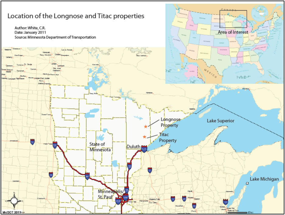
(image sourced from the Minnesota Department of Transportation)
Figure 3.1: Location of the Titac property
The Project Area is approximately centered at: (Coordinate system: Universal Trans Mercator, Zone 15 North, North American 1983 Datum) 568,000 m East, 5,228,000 m North. CIOUS has a mineral lease on 1402 acres (567 hectares) at the Project Area.
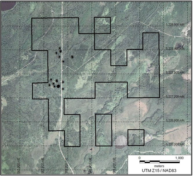
Properties in Minnesota are defined using the Township and Range, Section, quarter-section, quarter-section, quarter-section method. Sections are marked by corner posts; however, corner posts are not always present. CIOUS has conducted a geographical location survey on the Project Area. This survey mainly focused on locating historical drill collars and the original sampling grid cut baseline. An in-depth property boundary survey has not been completed; however, the property boundaries have been located on aerial photographs (Figure 3.2) .
| DJF_MJ/WB | Titac-NI43-101Rpt (4).docx | January 27, 2012 |
| 2CC031.004 – Cardero Resources | |
| Titac Project NI 43-101 | Page 20 |
|
Figure 3.2: Titac Property boundary with drill collar locations | |
|
Known zones of mineralization at the Project Area are approximately centered at: (Coordinate system: Universal Trans Mercator, Zone 15 North, North American 1983 Datum), 568,130 m East, 5,228,310 m North (Titac North); and 568,000 m East, 5,227,500 m North (Titac South). There have been no commercial mining operations at the Project Area. | |
| 3.1 |
Mineral Tenure |
|
Minerals in Minnesota are typically held as fee simple interests; either as part of the overall land estate or as a separate property interest. In many cases, ownership of the mineral estate has been severed from the surface estate, and may be held by a different owner. Although title to the mineral estate is often held by the State of Minnesota or the US Federal government, there are significant areas of private mineral ownership in Minnesota. Thus, there is often split-estate ownership, where the person or entity owning the surface may be, and often is, different than the person or entity that owns the mineral rights. Additionally, mineral rights themselves may also be split (e.g. the hydrocarbon rights owner may be different than the non-hydrocarbon mineral rights owner). United States law indicates that in split-estate situations, mineral rights are the dominant estate and have precedence over all other property rights (including surface). However, the mineral rights owner must have due regard for the surface estate and only occupy/use those portions of the surface that are necessary for mineral development. | |
|
Land holdings at the Project Area are a split-estate wherein St Louis County (the “County”) holds the surface rights, and a private mineral owner holds the mineral rights. CIOUS has entered an authorization agreement with the County dated June 11, 2008, pursuant to which CIOUS is authorized, on a non-exclusive basis, to enter upon the surface lands and conduct drilling operations, subject to compliance with applicable laws and the County’s approval of the specific drilling plans of CIOUS. CIOUS pays the County a fixed fee per bore hole drilled, and has agreed to carry out all required reclamation and indemnify, save and hold harmless the County. |
| DJF_MJ/WB | Titac-NI43-101Rpt (4).docx | January 27, 2012 |
| 2CC031.004 – Cardero Resources | |
| Titac Project NI 43-101 | Page 21 |
| 3.2 |
Titac Interest |
|
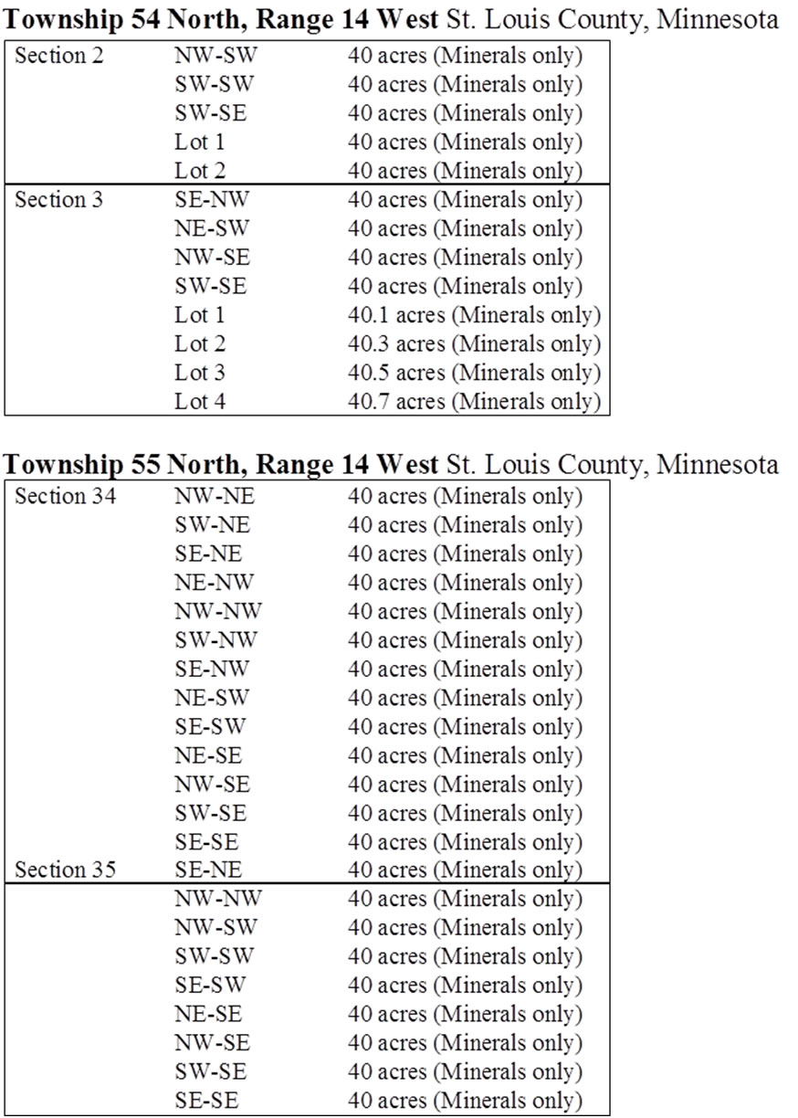
CIOUS has entered into a mining lease with a private mineral owner over an aggregate of 1,402 acres (567 hectares) of mineral rights located in sections 2 and 3 of Township 54 North and sections 34 and 35 of Township 55 North, all Range 14 West, St. Louis County, Minnesota (Table 1). The mining lease covers any mineral substance of a metalliferous nature, including those intermingled or associated materials or substances, recovered from each tonne of crude ore for the purpose of extracting iron (essentially, iron, titanium and vanadium). All other minerals are reserved to the private mineral owner. | |
|
The initial term of the mining lease is for a period of 20 years, commencing July 1, 2009, provided that the lease may be extended for an additional 5 year period if CIOUS gives notice at least 180 days prior to the end of such term, and has either paid to the owner at least USD $10,000,000 in royalties or pays to the owner the difference between the royalties actually paid and USD $10,000,000. In like manner, the lease can be extended for up to three additional 5 year terms, provided that the appropriate notice is given and that CIOUS has paid to the owner at least USD $5,000,000 in royalties during the previous 5 year term (or pays any deficiency in cash). CIOUS can terminate the lease at any time on sixty days' notice. CIOUS is required to make a bonus payment of USD $2,500 upon entering into the lease, plus yearly rental payments under the lease of: |
| • | the greater of USD $2,500 and USD $2/acre in years one and two; | |
| • | the greater of USD $5,000 and USD $5/acre in years three through five; | |
| • | the greater of USD $7,500 or USD $10/acre in years six through ten; | |
| • | the greater of $USD 10,000 or USD $25/acre in years eleven through fifteen; and | |
| • | the greater of USD $50,000 or USD $50/acre in years sixteen through twenty. |
These rental payments cease upon the commencement of commercial production, following which yearly minimum royalty payments of USD $200,000 apply. Following the commencement of commercial production, CIOUS is required to pay a royalty of USD $0.85 per ton of crude iron ore (adjusted quarterly based on variation in the quoted price of certain iron ore products) and 5% of the net return values (calculated in accordance with the provisions of the lease) for any other products produced (subject to a minimum royalty of USD $0.02 per pound of titanium). CIOUS is required to incur minimum work expenditures of USD $50,000 prior to the second anniversary of the lease, and USD $50,000 per year thereafter (any deficiency being payable in cash to the owner). Up to October 31, 2011, CIOUS had incurred an aggregate of USD $1,802,121 in expenditures and made all of the required rental payments to July 1, 2011.
| DJF_MJ/WB | Titac-NI43-101Rpt (4).docx | January 27, 2012 |
| 2CC031.004 – Cardero Resources | |
| Titac Project NI 43-101 | Page 22 |
Table 3-1: Mineral Tenure Information
| DJF_MJ/WB | Titac-NI43-101Rpt (4).docx | January 27, 2012 |
| 2CC031.004 – Cardero Resources | |
| Titac Project NI 43-101 | Page 23 |
| 3.3 |
Permits and Authorization |
|
All licenses, permits, and registrations required to conduct exploratory drilling in Minnesota have been obtained by CIOUS, and are up to date. The required licenses, permits, and registrations that CIOUS has obtained are listed below: |
| • |
Licensed Exploratory Borer with the Minnesota Department of Natural Resources (MDNR); License number: A10-0102 (annual renewal); | |
| • |
Licensed Explorer Company with the Minnesota Department of Health (MDH); License number 2850 (annual renewal); | |
| • |
Licensed Explorer Responsible Individual with the Minnesota Department of Health: License number: 2841 (Chris White; lifetime license); | |
| • |
Permit for drilling in wetlands with the United States Army Corp of Engineers for both properties (Permit expires on August 22, 2011); | |
| • |
Permit with the St. Louis County highway department to install temporary gravel access points along St. Louis County highway 4 to access specific areas of the Project Area (renewed as required); and | |
| • |
Storm Water Pollution Prevention Plan Permit (SWPPP) with the Minnesota Pollution Control Agency for each property (permit open until project completion, must notify MPCA upon completion of project for closure of permit). |
| 3.4 |
Environmental Considerations |
|
MDH regulations require that CIOUS must file a drill plan with the MDNR and the MDH at least 14 days prior to drilling operations, and the Explorer Responsible Individual must file well abandonment forms with the MDNR and the MDH within 30 days of completing each drill hole, and that exploratory bore holes must be sealed upon completion of drilling in compliance with MDH rules and regulations. Upon filling an initial drill plan CIOUS may begin drilling operations after 14 days, and may revise, or expand the drill plan by notifying the MDNR and MDH within 1 day of executing the new drill plan. MPCA regulations state that any ground disturbance greater than 1 acre requires the development, approval, and institution of a SWPPP. The plan must be drafted by a person, or persons certified by the MPCA, and a certified SWPPP site manager must oversee implementation of the plan, and application of the plan throughout the duration of the project. This plan must be modified as the project progresses to reflect any change in operations that warrant additional or different pollution prevention measures. CIOUS’s consulting geologist, Chris White, has obtained the proper certification with the MPCA to draft the SWPP, and to act as the SWPPP site manager; and Warren Johnson, a CIOUS contractor, is a certified SWPPP contractor with the MPCA. Chris White has been retained by CIOUS to oversee the overall and day-to-day project operations, and Warren Johnson’s company has been retained to install all drill trails and drill pads at the Project Area. |
| DJF_MJ/WB | Titac-NI43-101Rpt (4).docx | January 27, 2012 |
| 2CC031.004 – Cardero Resources | |
| Titac Project NI 43-101 | Page 24 |
| 4 |
Accessibility, Climate, Local Resources, Infrastructure and Physiography |
| 4.1 |
Accessibility |
|
Accessibility is excellent, with the Project Area located along a paved county highway. | |
|
The Project Area is located approximately 24.5 miles (39.4 km) south of Aurora, Minnesota. CIOUS is leasing a large portion of an old school building (Cina Building, 200 S. 2nd St. E., Aurora, MN 55705) in Aurora, Minnesota that serves as a field office, a drill core logging, preparation, and sampling facility, and a drill core, coarse sample, and sample pulp storage facility. | |
|
To access the Project Area from Aurora, MN: Beginning at the intersection between St. Louis County highway 99 and St. Louis County highway 110, travel south on St. Louis County highway 99 for 11.0 miles (17.7 km). Turn right, traveling west on St. Louis County highway 16 for 2.2 miles (3.5 km). Turn left, traveling south on St. Louis County highway 4 for 16.6 miles (26.7 km) to Marshall Trail. | |
| 4.2 |
Local Resources and Infrastructure |
|
The population of Aurora, Minnesota is approximately 1,850, and the nearby city of Hoyt Lakes, Minnesota (5 miles east of Aurora) has a population of approximately 2,000 people. Duluth, Minnesota (pop. 84,419) is located approximately 30 miles (48.3 km) south of the Project Area. Virginia, Minnesota (pop. 8,481) is located approximately 70 miles (112.7 km) west-northwest of the Project Area. | |
|
Northeastern Minnesota has been supporting mining activities since the Soudan mine opened in 1882. Currently, northeastern Minnesota facilitates six taconite (iron ore) mines located approximately within 100 miles (161 km) west-northwest of the Project Area in the Iron Range of Minnesota in the Virginia, and Hibbing, Minnesota area. When at full production, the taconite (iron ore) mining industry directly employs nearly 4,000 people in northeastern Minnesota. | |
|
The infrastructure in northeastern Minnesota related to mining activities is excellent with low cost electricity, railroads, paved state and county highways, international shipping ports, mining professionals, mining vendors, and trained labor all readily available. International shipping ports are located along the north shore of Lake Superior including Duluth/Superior, Silver Bay, Taconite Harbor, and Two Harbors with linked rail systems to all. | |
|
Northeastern Minnesota is easily accessible through air travel with three airports located within 60 miles (96.5 km) of Hoyt Lakes, Minnesota including the Eveleth Virginia Municipal Airport located in Virginia, Minnesota; the Range Regional Airport (“RRA”), located in Hibbing, Minnesota; and the Duluth International Airport (“DIA”), located in Duluth, Minnesota. Commercial flights are offered by Delta Airlines at RRA and DIA, and also by Allegiant Air at DIA. The Minneapolis/St. Paul airport is located approximately 200 miles (321.7 km) south of Hoyt Lakes, Minnesota. Connecting flights are available from Minneapolis/St. Paul to both DIA, and RRA. | |
|
The Laskin Energy Center is located near Hoyt Lakes, Minnesota (less than 25 miles, or 40 km, from the Project Area), providing 110 megawatts of electric service. The DM&IR (Canadian National) railway services the Laskin Energy Park, located next to the Laskin Energy Center. The Laskin Energy Park also provides natural gas, water and waste water, and industrial steam power services. |
| DJF_MJ/WB | Titac-NI43-101Rpt (4).docx | January 27, 2012 |
| 2CC031.004 – Cardero Resources | |
| Titac Project NI 43-101 | Page 25 |
|
The Erie plant (formerly owned by LTV Steel Mining Company and currently owned by Polymet Mining Corporation), a large crushing, grinding, and milling facility, is located approximately 14 miles (22.5 km) west-northwest of the Aurora. The Erie plant was built in the 1950’s, and processed approximately 100,000 tons of taconite (low-grade iron) ore per day until 2001 when LTV Steel Mining Company filed for bankruptcy. Polymet intends to use the Erie plant to process the copper- nickel-platinum group element ore from its NorthMet deposit, and estimates that the plant will provide 400 full-time jobs. | |
|
The Steel Dynamics, Inc., Mesabi Nugget plant is located just north of Hoyt Lakes, Minnesota. Mesabi Nugget uses an innovative direct-reduction process to produce pig-iron nuggets. Production began at Mesabi Nugget in December of 2009, and the plant has a capacity to produce 500,000 tonnes of pig-iron nuggets a year. The Mesabi Nugget plant currently provides approximately 90 full- time jobs. | |
| 4.3 |
Climate |
|
The climate in northeastern Minnesota is mid-continental. Winter conditions usually begin in mid- December and last until mid-March, with frozen ground beginning in late-December to early-January. The spring thaw usually begins in mid-March to late-April, with stable, dry spring-summer-fall conditions occurring from late-April to mid-December. Table 4.1 below displays the monthly average temperatures and precipitation for the Hoyt Lakes area. |
Table 4.1: Average monthly temperatures and
precipitation for the Hoyt Lakes, Minnesota
area (data from weather.com)
MONTH |
Avg. High Temp (degrees F) |
Avg. Low Temp (degrees F) |
Avg. Precipitation (inches) |
| January | 16 | -14 | 0.76 |
| February | 24 | -8 | 0.7 |
| March | 35 | 6 | 0.99 |
| April | 51 | 22 | 1.57 |
| May | 65 | 33 | 3.05 |
| June | 73 | 43 | 4.49 |
| July | 77 | 48 | 4.42 |
| August | 75 | 45 | 4.29 |
| September | 65 | 36 | 4 |
| October | 52 | 26 | 2.9 |
| November | 34 | 12 | 1.33 |
| December | 20 | -5 | 0.61 |
| DJF_MJ/WB | Titac-NI43-101Rpt (4).docx | January 27, 2012 |
| 2CC031.004 – Cardero Resources | |
| Titac Project NI 43-101 | Page 26 |
| 4.4 |
Physiography |
|
Topographic relief on the Project Area is generally low, and the surface is flat-laying. Elevations range between 470 m and 490 m. The ground cover is a mixture of Palustrine, forested wetlands (Cowardin classification system), and higher dry forested ground (Figure 4.1). Bug creek runs through the Project Area. Overburden, consisting of glacial till composed of pebbles, cobbles, and boulders within a sand and clay matrix, covers much of the property. Depth to bedrock is generally between 20 m and 30 m. |
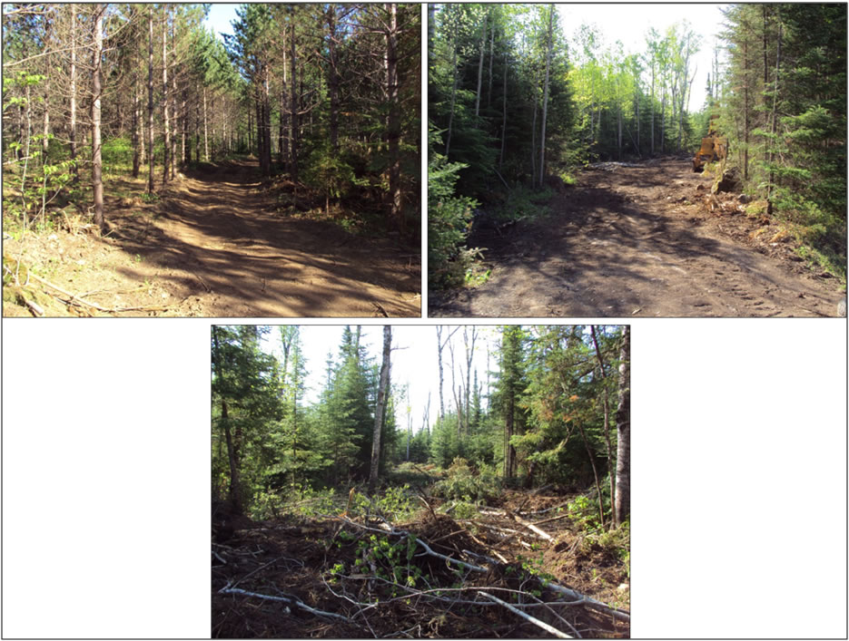
Figure 4.1: Typical Landscape in the Project Area
| DJF_MJ/WB | Titac-NI43-101Rpt (4).docx | January 27, 2012 |
| 2CC031.004 – Cardero Resources | |
| Titac Project NI 43-101 | Page 27 |
| 5 |
History |
|
Northeastern Minnesota has a strong history of iron and taconite mining, as well as copper, nickel, and platinum group element exploration. Titaniferous iron deposits were first discovered in northeastern Minnesota in the mid to late 1800’s in the northern portion of the Duluth Complex. Additional titaniferous iron deposits were discovered in the southern part of the Duluth Complex in the mid to late 1900’s during reconnaissance exploration for copper and nickel. | |
| 5.1 |
Titaniferous Iron Oxide Mineralization in the Duluth Complex |
|
In 1967 several companies began exploring magnetic anomalies delineated from state geophysical surveys in the southern part of the Duluth Complex. Exploration drilling targeted these magnetic anomalies searching for copper-nickel sulfide mineralization. While copper-nickel sulfide mineralization was intersected in many drill holes, the magnetic anomalies were largely composed of titaniferous-iron oxide mineralization. At the time these intrusions were generally thought to be of little importance, because copper-nickel grades were too low to have economic significance during that time period. However, several titaniferous iron oxide intrusions have been explored in detail. The following summarizes the known history of the Project Area. | |
| 5.2 |
Titac Property |
|
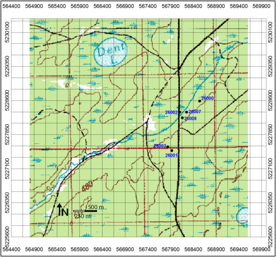
Exploration of the Project Area, historically known as Section 34, has been limited, though several exploratory bore holes and geophysical surveys have been completed. United States Steel Corp. (USSC) drilled six holes into the Section 34 OUI following a ground magnetic survey conducted in the mid 1960’s by USSC (Figure 5.1). Exploration of Section 34 was part of a larger exploration program in which USSC drilled holes into numerous magnetic anomalies, delineated during state run airborne geophysical surveys, proximal to the western contact of the southern portion of the Duluth Complex. USSC was exploring for copper-nickel sulfides, which were intersected, however, the magnetic anomalies were created by titanium-iron oxide mineralization. Three of the six initial drill holes at Titac (Section 34) intersected strong titanium-iron mineralization throughout their length, while the remaining three holes intersected various apophyges of titanium-iron mineralization (Severson, 1995). To the best of the authors’ knowledge no other exploration has been conducted at the Project Area (Section 34), until the recent (2010-2011) exploration by CIOUS, in which 32 boreholes were completed at the property. |
| DJF_MJ/WB | Titac-NI43-101Rpt (4).docx | January 27, 2012 |
| 2CC031.004 – Cardero Resources | |
| Titac Project NI 43-101 | Page 28 |
|
Figure 5.1: Map showing the locations of historic diamond drill holes on the Titac property | |
| 5.2.1 |
Historic Titac and OUI Metallurgical Analysis |
|
Metallurgical test work has been completed on a variety of OUI bodies including the Titac deposit itself. | |
|
Testwork completed on Titac (then “Section 34”) was based upon composite samples collected from early drilling completed on Titac North. Tests were limited to Davis Tube testing to determine the fraction weight and chemical character of a magnetic fraction of crushed samples from drill core. Approximately 158 m (520 feet) of drill core was composited into two samples. The samples were crushed to minus 20 mesh and screened into two sizes at 150 mesh. Heavy liquid gravity concentrates were made, with the heavy concentrate further separated into magnetic and non/para- magnetic fractions. | |
|
Heavy liquid concentrates from these samples averaged 49 % Fe and 27.5 % TiO2 , compared to sample head grades of 42.7 % Fe and 22.5 % TiO2 . Magnetic separation produced a non-mag concentrate of 45-47 % TiO2 (Niles, H.B., 1971). |
| DJF_MJ/WB | Titac-NI43-101Rpt (4).docx | January 27, 2012 |
| 2CC031.004 – Cardero Resources | |
| Titac Project NI 43-101 | Page 29 |
The results of this work lead H.B. Niles to recommend quantifying the Titac material in order to determine if further testwork was warranted to further refine potential processing characteristics. More detailed testwork was completed on the Longnose OUI deposit, 40km north of Titac. This deposit is of a similar style to the Titac deposit.
Three bulk samples weighing 600 kg, 39 tonnes and 60 tonnes respectively were collected by American Shield Corp throughout the 1990s. The larger samples were collected from outcrop within the western part of the Longnose deposit. A processing flow sheet was developed and the sample was beneficiated by grinding, spiral separation, magnetic concentration, and dry high tension concentration. The first full-scale pilot plant run was made on October 3, 1994. (Coleraine Minerals, 1994).
Results of these larger scale tests indicated that it was possible to scale up creation of an ilmenite concentrate >45 % TiO2 as well as complete further beneficiation that results in a high grade TiO2 product suitable for the pigment market. (CMRL, 1994, 1996).
| DJF_MJ/WB | Titac-NI43-101Rpt (4).docx | January 27, 2012 |
| 2CC031.004 – Cardero Resources | |
| Titac Project NI 43-101 | Page 30 |
| 6 |
Geological Setting and Mineralization |
| 6.1 |
Regional Geology |
|
The Project Area is located within the Superior Province of the Canadian Shield. The regional basement rocks are composed of Archean granitoid intrusions, metasedimentary rocks, and metavolcanic rocks; and Paleoproterozoic sedimentary rocks. Mafic flows, mafic and felsic intrusives, and related interflow sedimentary rocks cut these basement rocks during the development of the Mesoproterozoic Midcontinent Rift System (“MCR”). | |
|
The Midcontinent Rift System stretches from Lake Superior to Iowa (Figure 6.1), and is largely buried by sediments; however MCR bedrock is relatively well exposed in the Lake Superior region. In northeastern Minnesota the MCR is dominantly composed of several groups of rocks including: the North Shore Volcanic Group (NSVG), the Beaver Bay Complex, and the Duluth Complex. The roof zone of the MCR is largely composed of NSVG lava flows, and the Duluth Complex is generally the intrusive equivalent of the NSVG lava flows. |
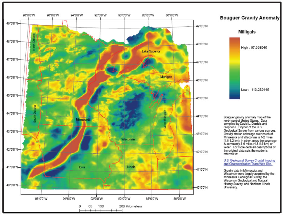
Figure 6.1: Bouguer Gravity Anomaly shows the Mid Continent Rift
Figure 6.1 shows the Bouger Gravity
Anomaly which extends from Lake Superior through Iowa, USA, (source
eo.umn.edu/mgs/nicegeo/pdfs/boug_grav.pdf)
| DJF_MJ/WB | Titac-NI43-101Rpt (4).docx | January 27, 2012 |
| 2CC031.004 – Cardero Resources | |
| Titac Project NI 43-101 | Page 31 |
The multiple intrusions of the Duluth Complex occur within an arcing band from Duluth to near the Canadian border that is 270 km long and up to 40 km wide. In terms of areal exposure, it is the second largest mafic intrusive complex on Earth after the Bushveld Complex of South Africa. The Duluth Complex is typically subdivided into four intrusive series based on dominant lithology, general age, and internal structure. In order of relative decreasing age, these series are the felsic series, the early gabbroic series, the anorthositic series, and the layered series (Miller et al., 2002). Field evidence suggests that the layered series intruded into the anorthositic series, however U-Pd dates obtained by Paces and Miller (1993) show that the anorthositic series and the layered series are virtually identical in age. This indicates that the layered series likely intruded into the anorthositic series when it was still quite warm, and possibly semi-molten. The anorthositic series has not been subdivided into individual intrusions; however the layered series has been shown to consist of at least 12 distinct mafic layered intrusions (Miller et al., 2002; Figure 6.2) .

Figure 6.2: Geologic Map of northeastern Minnesota
Figure 6.2 displays the Duluth Complex and associated formations with the layered series intrusions. Lithology codes include: TI – Tuscarora intrusion, L1T – Lake One Troctolite, WLI – Wilder Lake intrusion, SKI – South Kawishiwi intrusion, BEI – Bald Eagle intrusion, OLI – Osier Lake intrusion, GLI – Greenwood Lake intrusion, PRI – Partridge River intrusion, WMI – Western Margin intrusion, BLI – Boulder Lake intrusion, DLS – Layered Series at Duluth (Miller et al. 2002).
| DJF_MJ/WB | Titac-NI43-101Rpt (4).docx | January 27, 2012 |
| 2CC031.004 – Cardero Resources | |
| Titac Project NI 43-101 | Page 32 |
| 6.2 |
Property Geology |
|
| |
|
Several layered series intrusions host numerous OUIs in the Duluth Complex, including (from north to south) the Partridge River intrusion, the Western Margin intrusion, and the Boulder Lake intrusion. All known OUIs occur proximal to the western contact of the Duluth Complex in a straight line beginning just south of Babbitt, Minnesota, and ending just north of Duluth, Minnesota. Known OUI intrusions in the Duluth Complex include Section 17, Longear, Longnose, Section 22, Skibo, Water Hen, Section 34 (Titac), Boulder Creek, Boulder Lake North, and Boulder Lake South. Oxide Ultramafic intrusions cut the layered series intrusions, and are generally regarded as late occurring events in the development of the MCR. Geometrically, OUIs have various shapes and sizes including pipe-like, sheet-like, and funnel-like, and their emplacement may be structurally controlled (Severson, 1995). | |
|
| |
| 6.3 |
Geology of the Titac Property |
|
| |
|
Little was known about the Project Area at the time of CIOUS’s acquisition of the property. There is no exposed bedrock on the property, as glacial till covers the area, and only six diamond drill holes had been drilled on the property prior to 2010. Everything that is known about the geology of the property comes from geophysical surveys, six historic diamond drill holes, and 32 holes drilled by CIOUS in 2010 and 2011 (Figure 6.3). | |
|
| |
|
A ground magnetic survey conducted by USSC in the 1960’s, and re-interpreted for Cardero by Quantec in 2010 demonstrates that the Titac intrusion consists of numerous strongly magnetic intrusions (Figure 6.3). Drill core shows that the Titac intrusion is hosted by troctolite and augite troctolite of the Western Margin intrusion, and that there is also a large fraction of anorthositic rocks, which are likely inclusions, or roof pendants of the anorthositic series within the Western Margin intrusion. |
| DJF_MJ/WB | Titac-NI43-101Rpt (4).docx | January 27, 2012 |
| 2CC031.004 – Cardero Resources | |
| Titac Project NI 43-101 | Page 33 |
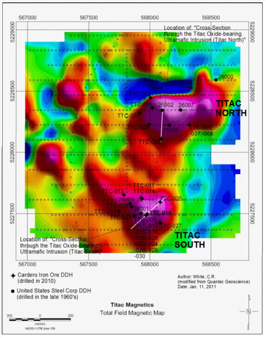
Figure 6.3: Magnetic map of the Project Area
Figure 6.3 shows ground magnetic data re-interpreted 1967 USSC ground geophysical survey, showing survey, showing the Titac North, and Titac South OUIs, as well as the six historic diamond drill holes and 30 Cardero 2010 diamond drill holes on the property, and the location of the cross-sections in figures 7-8 (through Titac South) and 7-9 (through Titac North)
| DJF_MJ/WB | Titac-NI43-101Rpt (4).docx | January 27, 2012 |
| 2CC031.004 – Cardero Resources | |
| Titac Project NI 43-101 | Page 34 |
There are two large intrusions at Titac, herein referred to as Titac North and Titac South (Figure 6.3), with numerous smaller intrusions to the west and northwest of the two main intrusions. Titac North is approximately 500 m north of Titac South. Titac North is approximately 600 m long, between 180 m and 330 m wide, and is at least 450 m thick (the deepest vertical hole at Titac North measures 275 m in length, and ends in titanium-iron oxide mineralization; however, diamond drill hole TTC-005-2010 was an inclined hole that reached a depth of approximately 450 m. Titac South is approximately 270 m by 260 m in dimension, and is at least 490 m thick (the deepest vertical hole at Titac South measure 488 m in length, and ends in titanium-iron oxide mineralization). None of the remaining intrusions at Titac have been drilled.
The Titac intrusion or intrusions dominantly consist of coarse-grained to pegmatitic pyroxenite and peridotite as defined by the Severson and Hauck (1990) rock classification scheme for Duluth Complex rocks (Figure 6.4), with lesser amounts of medium- to coarse-grained dunite, and numerous zones of massive and semi-massive oxide (45-100% titanium-iron oxide mineralization). Pyroxenite, peridotite, and dunite typically contain 15-35% titanium-iron oxide mineralization. Locally, contacts between the Titac OUI intrusions and the hosting country rock are marked by fine- to medium-grained melatroctolite, which features sub-vertical serpentine veining. Contacts between lithologies within the OUI, or OUIs can be sharp or gradational, however they are usually sharp (cm to m).
Both Titac North and Titac South appear to be vertical pipe-like intrusions, with complex sub-vertical sheet-like, and/or zoned stratigraphies/lithological variations (Figures 6.5 and 6.6) . Both Titac North and Titac South are open at depth.
| DJF_MJ/WB | Titac-NI43-101Rpt (4).docx | January 27, 2012 |
| 2CC031.004 – Cardero Resources | |
| Titac Project NI 43-101 | Page 35 |
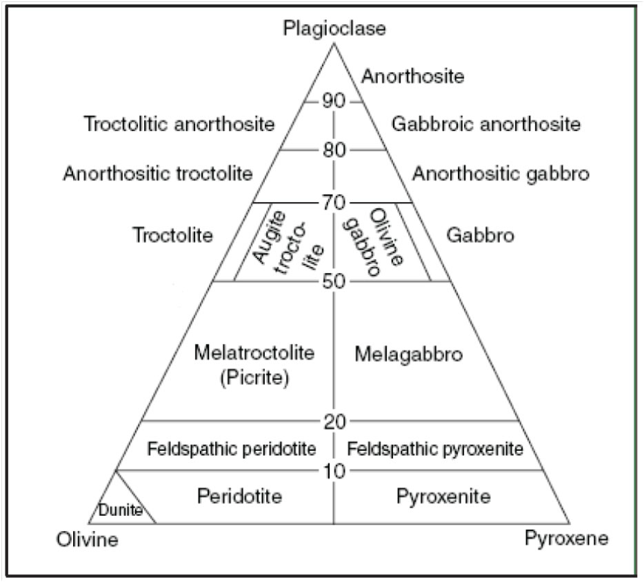
Figure 6.4: Rock classification scheme for Duluth Complex rocks, after Severson and Hauck, 1990
| DJF_MJ/WB | Titac-NI43-101Rpt (4).docx | January 27, 2012 |
| 2CC031.004 – Cardero Resources | |
| Titac Project NI 43-101 | Page 36 |
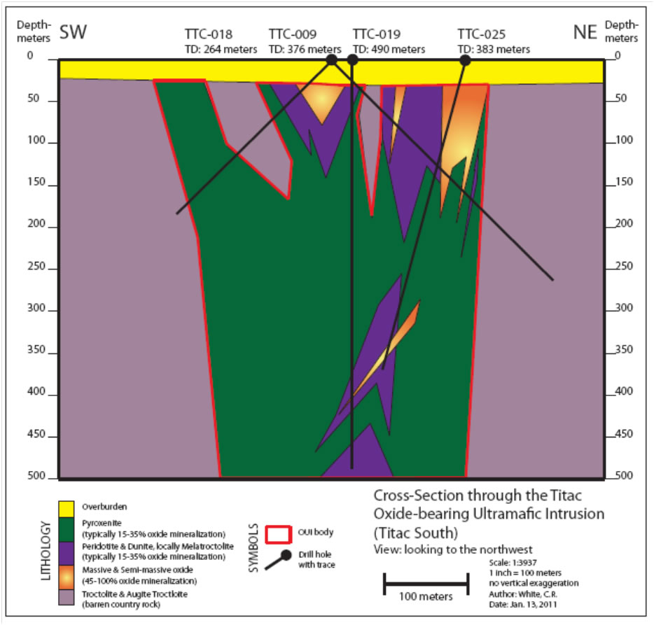
Figure 6.5: Schematic cross-section through the Titac Oxide-bearing Ultramafic Intrusion (Titac South)
| DJF_MJ/WB | Titac-NI43-101Rpt (4).docx | January 27, 2012 |
| 2CC031.004 – Cardero Resources | |
| Titac Project NI 43-101 | Page 37 |
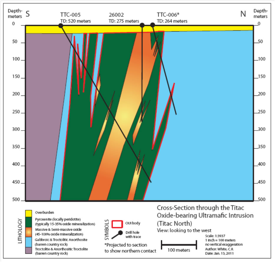
Figure 6.6: Schematic cross-section through the Titac Oxide-bearing Ultramafic Intrusion (Titac North)
| 6.4 |
Mineralization at Titac |
|
Titaniferous-iron oxide mineralization at Titac consists of disseminated to net-textured, medium- to course-grained, magnetite and ilmentie with some fraction of titaniferous magnetite. It is quite difficult to tell the difference between titanium-rich mineralization and iron-rich mineralization in hand sample, however the general statement could be made that drill core exhibiting a dark-silvery color is ilmenite-rich, drill core exhibiting a dull-black color is rich in titaniferous magnetite, and drill core exhibiting a shiny-black color is magnetite-rich. Olivine-rich ultramafic rocks (peridotite, feldspathic peridotite, and dunite) host the majority of the titanium-iron oxide mineralization found in the Titac OUI, and will often be net-textured with oxide minerals interstitial to silicates. When mineralization is hosted by olivine-rich ultramafic rocks it is typically medium- to coarse-grained, disseminated to net- textured, and interstitial to silicate minerals. However, when the mineralization is hosted by pyroxenite, the oxide mineralization typically occurs as medium- to coarse-grained clumps or clots up to approximately 5 cm in size (typically 2-4 cm). |
| DJF_MJ/WB | Titac-NI43-101Rpt (4).docx | January 27, 2012 |
| 2CC031.004 – Cardero Resources | |
| Titac Project NI 43-101 | Page 38 |
The Titac intrusion also contains abundant copper-sulfide mineralization. Up to five modal percent (typically 1-2%) copper-sulfide mineralization has been observed, dominantly consisting of chalcopyrite and bornite. Two distinct types of chalcopyrite seem to be present including a bright, golden, metallic colored chalcopyrite and a second duller, brownish-bronze colored chalcopyrite. Bornite exhibits a deep blue-purple metallic color. Copper sulfides typically occur as medium- to coarse-grained disseminations interstitial to silicates and oxides, but also occur as pegmatitic clots up to approximately 5 cm in size (typically 2-3 cm). Very fine-grained disseminations of pyrrhotite can occur near the contacts of the OUI and the country rock (in both OUI rocks and country rocks), and rarely fine-grained pyrite will fill micro-fractures (<1 to 2 mm thick) within the OUI.
Mineralization at Titac North appears to be vertically continuous, as historic diamond drill hole 26002 was drilled vertically near the center of Titac North (Figure 6.6), and encountered strongly mineralized pyroxenite, and massive and semi-massive oxide throughout its length (~275 m). Mineralization at Titac South also appears to be vertically continuous as CIOUS diamond drill hole TTC-019-2010 was drilled vertically near the center of the Titac South (Figure 6.5) magnetic anomaly, and intersected strongly mineralized pyroxenite, peridotite, and numerous zones of massive and semi-massive oxide throughout its length (approximately 490 m). Titac North and Titac South appear to be somewhat laterally continuous as well, though there does seem to be anorthositic, locally basaltic, rarely sedimentary, and possibly troctolitic inclusions within both intrusions, and the lateral stratigraphy of both intrusions seems to be quite heterogeneous.
| DJF_MJ/WB | Titac-NI43-101Rpt (4).docx | January 27, 2012 |
| 2CC031.004 – Cardero Resources | |
| Titac Project NI 43-101 | Page 39 |
| 7 |
Deposit Types |
|
Titaniferous iron oxide intrusions within the Duluth Complex were first discovered in 1867, approximately coincident with the discovery of the Mesabi Range iron ores (Winchell, 1897). Broderick (1917) was the first to classify the intrusions while working in the northern part of the Duluth Complex, subdividing them into 4 groups: A) inclusions of Gunflint Iron-Formation, B) gabbroic banded segregations, C) irregular late intrusions of titaniferous magnetite, and D) dike-like intrusions of titaniferous magnetite. Severson (1988), and Severson and Hauck (1990) recognized types 3 and 4 while working in the western and southern portions of the Duluth Complex and reclassified them together as OUIs, based on their ultramafic composition, high oxide content, and cross-cutting relationships to the layered series troctolitic intrusions that host them. Hauck et al. (1997) reclassified Broderick’s (1917) subdivisions into three general types: Type 1, banded or layered, oxide-rich metasedimentary inclusions in mafic and ultramafic rocks; Type 2, banded or layered oxide segregations (cumulates) in mafic rocks; and Type 3, discordant OUIs with semi- massive to massive oxide zones. The Titac intrusion is classified as Type 3 titaniferous iron oxide intrusion (Hauck et al. 1997) as described below. | |
|
Type 3 titaniferous iron oxide intrusions in the Duluth Complex are somewhat similar to the ultramafic intrusions of the Bushveld Complex, the Stillwater Complex, and the Rio Jacare Intrusion of Brazil (Hauck et al. 1997). They are typically composed of coarse-grained to pegmatitic, oxide- bearing (>5% to 30% oxide minerals) pyroxenite, peridotite, and dunite, which contain lenses of semi-massive (>30% to 90% oxide minerals) and massive oxide (>90% oxide minerals). OUIs in the Duluth Complex vary in size and shape, but generally seem to occur as sheet-like intrusions (sills), funnel-like intrusions, dike-like intrusions, or pipe-like intrusions. They can be zoned with numerous apophyses around a centralized ultramafic core. When they are zoned, they tend to feature pegmatitic pyroxenite generally surrounding a core of coarse-grained to pegmatitic peridotite and dunite. They appear to be deep-seated and several Duluth Complex OUIs seem to be root-less. Genesis of the Duluth Complex OUIs is speculative and several theories have been proposed as described below: |
| 1) |
Severson (1988, 1991, and 1994), and Severson and Hauck (1990) suggest that a spatial/empirical relationship between the Duluth Complex OUIs and the Biwabik Iron-Formation exists, and that incorporation of the Biwabik Iron-Formation by the Duluth Complex at the basal contact may have inspired the genesis of the Duluth Complex OUIs. This does not directly explain the high titanium content of the Duluth Complex OUIs however; Muhich (1993) finds that the Biwabik Iron-Formation is locally enriched in titanium proximal to the Duluth Complex basal contact. Muhich’s (1993) observations suggest that the Duluth Complex OUIs may be genetically related to the Biwabik Iron-Formation, and may be assimilated inclusions of Biwabik Iron-Formation that have been enriched in titanium and iron from Duluth Complex magmas and fluids. | |
| 2) |
Severson (1988, 1994) and Severson and Hauck (1990) also suggested, as did Ross (1985) that Duluth Complex OUIs formed by infiltration metasomatism. Infiltration metasomatism calls on the upward streaming of intercumulus fluids that are derived from within a crystallizing cumulus pile, or more simply put, the magma itself. This genesis mechanism has been suggested for the formation of similar ultramafic plugs in the Bushveld Complex (Schiffries, 1982; Viljoen and Scoon, 1985). |
| DJF_MJ/WB | Titac-NI43-101Rpt (4).docx | January 27, 2012 |
| 2CC031.004 – Cardero Resources | |
| Titac Project NI 43-101 | Page 40 |
| 3) |
Bonnichsen (1972) and Mainwaring and Naldrett (1977) suggested a magmatic origin for the Duluth Complex OUIs. In this empirical magmatic genesis model, the Duluth Complex OUIs would form from ferrogabbroic magmas, containing an abundance of suspended plagioclase crystals which separate from the magma and rise to the top of the magma chamber due to density contrasts, subsequently leaving the much more dense iron-rich titaniferous ultramafic magma toward the bottom. |
Evidence for all three genesis models exists, thus all three models, or a combination of the three may be accurate in specific instances. Mineralization at Titac appears to be largely intrusive in nature, but also exhibits textures near contacts with country rock that could be metasomatic in nature. It also seems apparent that in some instances Biwabik Iron formation could have influenced mineralization, based on the proximity of some OUIs to Biwabik Iron-Formation country rock. However, not all OUIs in the Duluth Complex show obvious proximity to occurrences of Biwabik Iron-Formation.
| DJF_MJ/WB | Titac-NI43-101Rpt (4).docx | January 27, 2012 |
| 2CC031.004 – Cardero Resources | |
| Titac Project NI 43-101 | Page 41 |
| 8 |
Exploration |
|
Exploration of the Project Area by CIOUS began in the summer of 2010 with field searches for historic drill collars. Benchmark Engineering (Mountain Iron, Minnesota) was contracted to conduct the search with key CIOUS personnel on hand to oversee the work. | |
|
No bedrock is exposed at the Project Area. Because of this, no bedrock mapping has been completed by CIOUS to date (January 2012). | |
|
An airborne geophysical survey was conducted by the Minnesota Geological Survey which provided the initial template for early exploration. A ground magnetic survey was conducted by USSC in 1967 on the Project Area and has been obtained by CIOUS. A map of this survey, including the original grid, reading stations, readings, and the collar location for the first drill hole drilled on the property (DDH 26000) was obtained from the archives at the Minnesota Department of Natural Resources office in Hibbing, Minnesota in 2010. This map has been georeferenced based on the drill collar and road locations. The grid and station locations were then converted to m in the Universal Trans Mercator projection, using the North American 1983 datum. The station locations and magnetic readings were then entered into a spreadsheet, and the data was re-interpreted by Quantec Geoscience. The results of this re-interpretation confirmed the presence of multiple titaniferous-iron oxide-bearing intrusions at the Project Area (Figure 8.1) including two large intrusions here referred to as Titac North and Titac South, as well as numerous smaller intrusions to the west and northwest. |
| DJF_MJ/WB | Titac-NI43-101Rpt (4).docx | January 27, 2012 |
| 2CC031.004 – Cardero Resources | |
| Titac Project NI 43-101 | Page 42 |
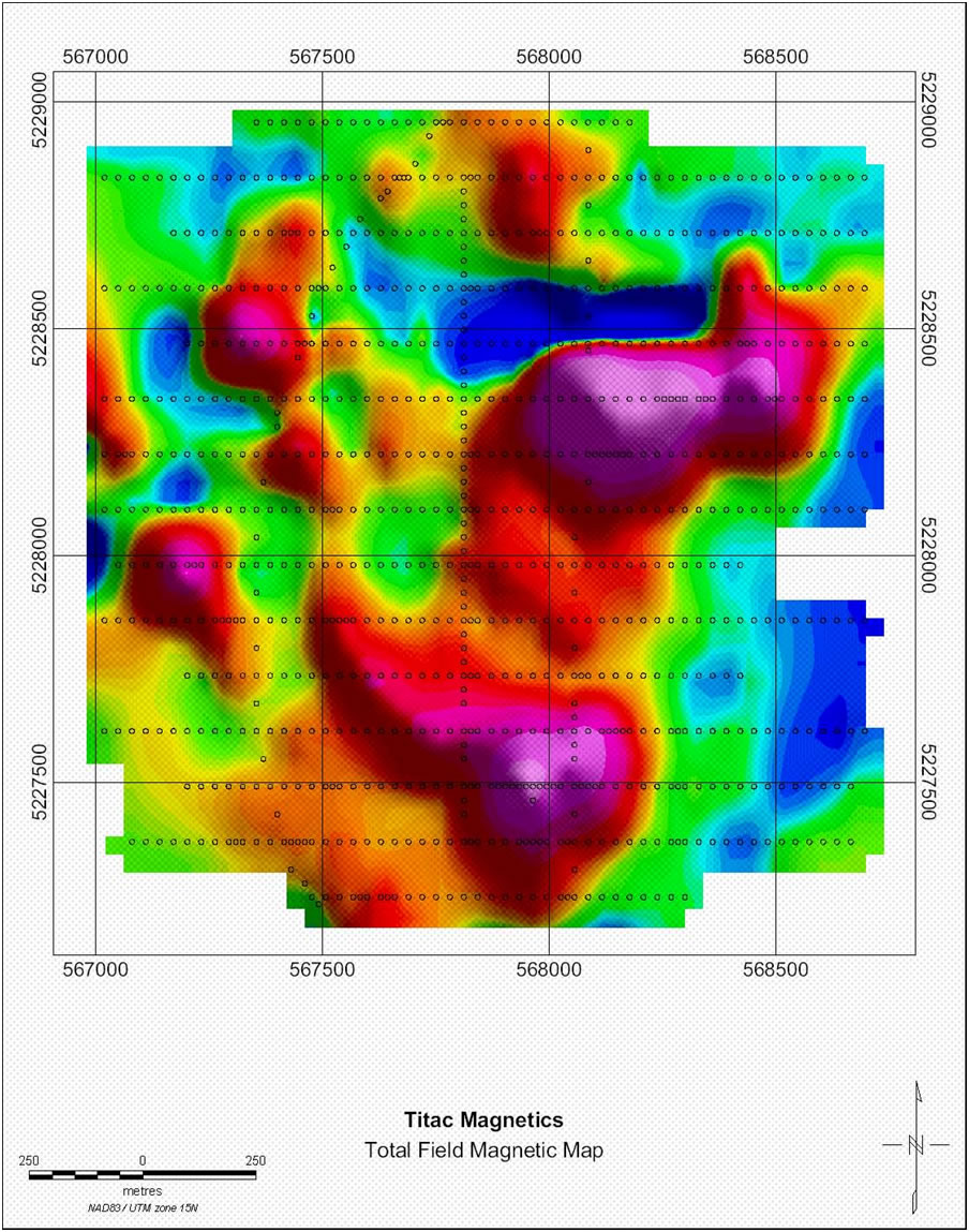
Figure 8.1: Re-interpretation of 1967 ground magnetic
data, confirms the presence of multiple
titaniferous-iron oxide-bearing
intrusions at Titac, including the two main intrusions
(Titac North and
Titac South)
| DJF_MJ/WB | Titac-NI43-101Rpt (4).docx | January 27, 2012 |
| 2CC031.004 – Cardero Resources | |
| Titac Project NI 43-101 | Page 43 |
| 9 |
Drilling |
|
CIOUS completed drilling of 32 NQ2 diamond drill holes totaling 11,034.4 m (36,202 feet) on the Project Area between February 2010 and April 2011. Drilling depths were recorded in feet, as is the standard in the US. Drilling was completed by licensed drilling contractor Idea International Drilling Ltd. (Idea). In 2010 Idea conducted drilling operations using four different drill rigs (Atlas Copco CS1000, Atlas Copco Diamec U6, Atlas Copco CT14, and a Sandvik DE130) with two rigs operating at any given point in time. Drill rigs were skid-mounted (with the exception of the Atlas Copco CT14), and maneuvered in the field using Caterpillar D5M and D7G tractors. In 2011 one Morooka mounted drill rig (Boart Longyear LF70) was utilized. Licensed contractor Warren Johnson Excavating was contracted to install all drill trails, drill pads, and entrance/exit points. Trails, pads, and entrance/exit points were installed using a combination of Caterpillar tractors, Caterpillar excavators, and various logging skidders. | |
|
All drill holes were permanently abandoned per Minnesota Department of Health standards, by setting a plug at least 300 feet below the surface of bedrock and filling the portion of the boring above the plug with neat cement. | |
|
Down-hole surveys have been completed on all contemporary drill holes. The Idea survey crew conducted down-hole surveys of each respective drill hole following completion of each hole. Down- hole surveys were completed using a Gyro-based tool, with survey readings collected every 20 feet. Data consists of a dip reading in degrees, and easting and northing readings in feet relative to the starting position of the survey. | |
|
Drill hole locations were recorded at the time of drilling using a hand held Garmin GPS unit with accuracy to +/- 6 m. Because casing was pulled upon completion of each drill hole, a steel fence post was used to mark the location of each hole. A location survey was completed by the Idea survey crew upon completion of drilling operations. Licensed surveyors Northern Lights Surveying and Mapping Inc. (Virginia, Minnesota) were contracted by Idea to place 4-5 location pins on site. Upon installation of these pins Idea surveyed drill hole locations with accuracy to 2/10ths of a foot, recording the easting, northing, and elevation of each drill hole. | |
|
There are also a number of historic drill holes that have been drilled on the Project Area. Only the drill holes completed prior to approximately 1970 have drill collars that still exist on site. These drill collars have been located and surveyed with a differential GPS. Since approximately 1970, drill casings have been mandated to be removed upon remediation of the drill site, so these drill collars do not exist. Evidence, such as drill pad clearings in the forest, has been found to support the location of many of these historic holes and their drill collar locations are believed to be within 10 m accuracy. | |
|
Tables 9.1a & b document the technical specifications of all contemporary and historic drilling at the Project Area. |
| DJF_MJ/WB | Titac-NI43-101Rpt (4).docx | January 27, 2012 |
| 2CC031.004 – Cardero Resources | |
| Titac Project NI 43-101 | Page 44 |
Table 9.1a: Contemporary and historic drilling at the Titac property
| TITAC PROPERTY CONTEMPORARY (drilled by Cardero Iron Ore Company Ltd.) | ||||||
| DDH# | (Survey) mE | (Survey) mN | Total Depth (ft) | Azimuth | Dip | Total Depth (m) |
| TTC-001-2010 | 568033.6 | 5228365 | 756 | Vertical | -90 | 230.4 |
| TTC-002-2010 | 568005.9 | 5228444.5 | 685 | Vertical | -90 | 208.8 |
| TTC-003-2010 | 567915.6 | 5228321 | 1196 | 130 | -60 | 364.5 |
| TTC-004-2010 | 567992.4 | 5228225.1 | 1137 | 73 | -60 | 346.6 |
| TTC-005-2010 | 568089.8 | 5228109.2 | 1707 | 0 | -60 | 520.3 |
| TTC-006-2010 | 568020.5 | 5228360.1 | 867 | 25 | -75 | 264.3 |
| TTC-007-2010 | 568317.8 | 5228222.7 | 1256 | 305 | -60 | 382.8 |
| TTC-008-2010 | 568320.2 | 5228220.8 | 1206 | 355 | -60 | 367.6 |
| TTC-009-2010 | 567966.7 | 5227486 | 1235 | 55 | -45 | 376.4 |
| TTC-010-2010 | 567743.4 | 5227519.3 | 1286 | 90 | -60 | 392 |
| TTC-011-2010 | 567965.7 | 5227490.9 | 894 | 115 | -45 | 272.5 |
| TTC-012-2010 | 567786.7 | 5227652.2 | 1276 | 130 | -60 | 388.9 |
| TTC-013-2010 | 567967.1 | 5227493 | 830 | 125 | -45 | 253 |
| TTC-014-2010 | 567933.4 | 5227620 | 1986 | 162 | -60 | 605.3 |
| TTC-015-2010 | 567970 | 5227486.2 | 855 | 165 | -45 | 260.6 |
| TTC-016-2010N | 567968.9 | 5227488.1 | 895 | 187 | -45 | 272.8 |
| TTC-017-2010 | 567928.4 | 5227630.4 | 1047 | 332 | -85 | 319.1 |
| TTC-018-2010 | 567961.5 | 5227486 | 865 | 219 | -45 | 263.7 |
| TTC-019-2010 | 567976.6 | 5227494 | 1607 | Vertical | -90 | 489.8 |
| TTC-020-2010 | 567968.2 | 5227482.8 | 1015 | 6 | -45 | 309.4 |
| TTC-021-2010 | 567873 | 5227482.3 | 1227 | 82 | -75 | 374 |
| TTC-022-2010 | 567964.5 | 5227489.5 | 1148 | 15 | -65 | 349.9 |
| TTC-023-2010 | 567849 | 5227555.2 | 1157 | 128 | -75 | 352.7 |
| TTC-024-2010 | 567970 | 5227486.7 | 1258 | 72 | -65 | 383.4 |
| TTC-025-2010 | 568083.8 | 5227592.6 | 1258 | 220 | -75 | 383.4 |
| TTC-026-2010 | 567965.4 | 5227482.8 | 1258 | 112 | -65 | 383.4 |
| TTC-027-2010 | 568081.9 | 5227423.5 | 1258 | 308 | -75 | 383.4 |
| TTC-028-2010 | 567966.3 | 5227483.9 | 1207 | 201 | -65 | 367.9 |
| TTC-029-2010 | 567964.1 | 5227486.6 | 1097 | 249 | -65 | 334.4 |
| TTC-030-2010 | 567964.2 | 5227489.7 | 1057 | 308 | -50 | 322.2 |
| TTC-031-2011 | 568025.2 | 5227537.0 | 903 | 341 | -45 | 275.2 |
| TTC-032-2011 | 568021.6 | 5227533.9 | 773 | 33 | -51 | 235.6 |
| DJF_MJ/WB | Titac-NI43-101Rpt (4).docx | January 27, 2012 |
| 2CC031.004 – Cardero Resources | |
| Titac Project NI 43-101 | Page 45 |
Table 9.2b: Contemporary and historic drilling at the Titac property
| TITAC PROPERTY HISTORIC (drilled by United States Steel Corporation) | ||||||
| DDH# | (Survey) mE | (Survey) mN | Total Depth (ft) | Azimuth | Dip | Total Depth (m) |
| 26000 | 568539 | 5228590 | 730 | 250 | -46 | 222.5 |
| 26001 | 567927 | 5227501 | 552 | Vertical | -90 | 168.2 |
| 26002 | 568100 | 5228342 | 901 | Vertical | 90 | 274.6 |
| 26003 | 567837 | 5227580 | 466 | Vertical | 90 | 142 |
| 26007 | 568250 | 5228343 | 587 | Vertical | 90 | 178.9 |
| 26008 | 568158 | 5228219 | 607 | Vertical | 90 | 185 |
| 9.1 |
Drilling Results |
|
| |
|
There are several OUIs at the Project Area of varying sizes. Only the two main intrusions (Titac North and Titac South) have been drilled, and only Titac South has been extensively drilled (Figures 9.1 and 9.2). The Titac North and Titac South OUIs both appear to be oriented sub-vertically, and appear to have complex igneous stratigraphies. The orientation and complexity of these intrusions have posed specific difficulties with regards for drill planning. | |
|
| |
|
Drilling at Titac North in the late 1960’s by USSC consists of three vertical holes drilled into the main intrusive intrusion, and a fourth angled hole drilled to the northeast of the main intrusion (Table 9.1). Strong titanium-iron oxide mineralization was intercepted in all three vertical holes drilled by USSC, while the fourth angled hole largely missed mineralization. CIOUS drilled a total of eight holes at Titac North in 2010. The first two holes (TTC-001-2010 and TTC-002-2010; Table 9.1) were vertical and largely missed mineralization, while the remaining six holes (TTC-003-2010 through TTC-008- 2010; Table 9.1) were angled and all intercepted strong titanium-iron oxide mineralization to varying degrees of success. Ground cover at Titac North is largely swamp land, and an early spring break- up in 2010 hampered drilling efforts by CIOUS, and forced drilling efforts to Titac South. | |
|
| |
|
Two holes were drilled at Titac South by USSC in the late 1960’s, both holes are vertical, and both holes intercepted thick intervals of strong titanium-iron oxide mineralization. Twenty-two holes in 2010 and two holes in 2011 were drilled at Titac South by CIOUS. Every hole at Titac South intercepted thick intervals of strong titanium-iron oxide mineralization. Given the sub-vertical orientation, and sheet-like or ring-like stratigraphy of the intrusion, the drill plan at Titac South featured a central fan or (inverted) funnel-like pattern of “inside-out” drill holes with various azimuths and dips (TTC-009,-011,-013,-015,-016,-018,-020,-022,-024,-026,-028,-029,-030-2010; Table 9.1). Numerous holes were also drilled “outside-in” toward the center of the intrusion (TTC-010,-012,- 014,-017,-021,-023,-025,-027-2010; Table 9.1). Drill hole density is good at Titac South, with a first round of holes drilled with a dip of -45 degrees (“°”)from the fan-site, and a second round of holes drilled with a dip of -65° from the fan-site. Holes drilled from the “outside-in” feature a similar pattern of dips. A vertical hole (TTC-019-2010) was also drilled at the fan-site to a depth of 490 m. Because of the sub-vertical orientation, and complex igneous stratigraphy at both Titac North and Titac South, the true thickness of specific mineralization intervals is not known, though the size and grade of both intrusions can be determined by three-dimensional modeling. | |
|
| |
|
Historical assays from the six holes drilled by USSC were favorable enough to lead Cardero to acquisition of the Project Area, however, re-assaying of historic core from the Project Area has not been conducted. Historical assays were not used in the estimation of the resource. |
| DJF_MJ/WB | Titac-NI43-101Rpt (4).docx | January 27, 2012 |
| 2CC031.004 – Cardero Resources | |
| Titac Project NI 43-101 | Page 46 |

Figure 9.1: Titac North drill holes
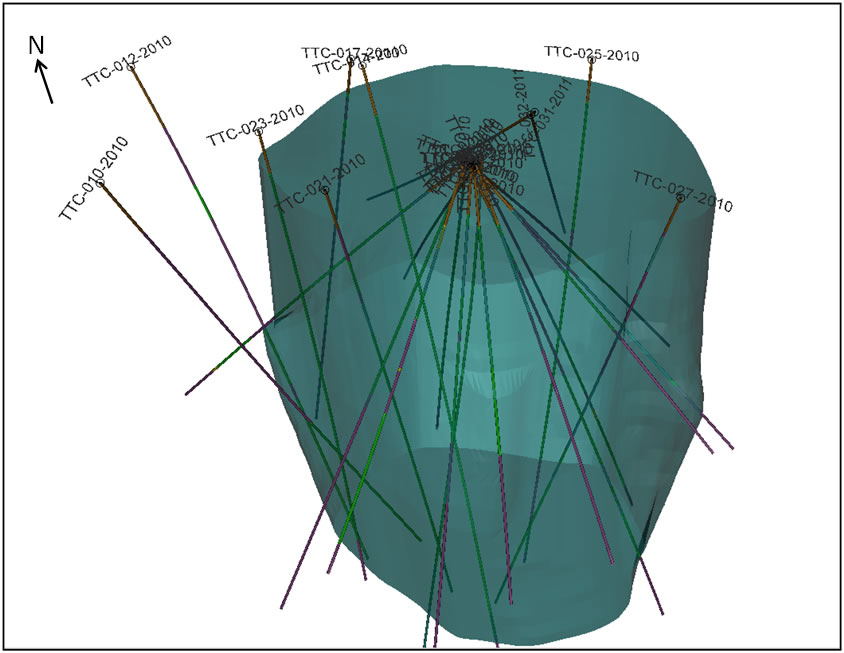
Figure 9.2: Titac South drill holes
| DJF_MJ/WB | Titac-NI43-101Rpt (4).docx | January 27, 2012 |
| 2CC031.004 – Cardero Resources | |
| Titac Project NI 43-101 | Page 47 |
| 10 |
Sample Preparation, Analyses, and Security |
| 10.1 |
Sampling Method and Approach |
|
All samples collected by CIOUS for analysis are from drill core. Drill core sampling is typically continuous through the length of each drill hole, except where drill core is obviously not mineralized. There are no sample biases, and samples are representative of the mineralization found. The rocks are intrusive and competent, typically with limited, localized fracturing. Drill core recovery averages 92.3% and rock quality is typically good. | |
| 10.2 |
Drill Core and Sample Interval Preparation |
|
Drill core is logged lithologically as it is drilled, and then stored in original cardboard boxes (10 feet per box) on pallets until additional analysis of core can be performed. As time permits, data is collected on core regarding rock quality, core recovery, magnetic susceptibility, and specific gravity. Sample intervals are then set-up, and all drill core is photographed. All drill core from the 2010 and 2011 drilling programs has been logged and sampled, and all sample results from the 2010 and 2011 drill core sampling campaign are complete. Lithology logging and collection of other data from drill core is done per standard industry practices as follows: | |
|
Lithology log | |
|
Lithology intervals are recorded in feet based on run blocks inserted at the time of drilling. Specific data is collected on rock type, texture, grain-size, lithology contacts, modal mineralogy, structures, oxide mineralization, sulfide mineralization, and alteration. | |
|
Rock quality/Core recovery | |
|
Intervals are recorded in feet based on run blocks inserted at the time of drilling. Actual lengths of intervals are measured and recorded in inches. The sum of all pieces of core greater than 4 inches is recorded, and total fractures per interval are recorded. RQD for each interval is determined by dividing the sum greater than 4 inches by the actual total inches of core recorded, and multiplying by 100. | |
|
Magnetic Susceptibility | |
|
Magnetic susceptibility data is collected on all drill core using a SAIC Exploranium KT-9 magnetic susceptibility meter. Five readings are collected for each core interval so that a reading is collected at least every 2 feet. | |
|
Specific Gravity | |
|
Specific gravity measurements are collected approximately every 20 feet. Core pieces measuring approximately 4-5 inches are weighed first in air (grams), and then in water (grams), using a manual balance and custom built work station. | |
|
Core photography | |
|
All drill core is photographed using a Sony Cyber-shot digital camera, typically with two core boxes per photo. All pictures are labeled as follows: “DDH Box # (#’-#’).” |
| DJF_MJ/WB | Titac-NI43-101Rpt (4).docx | January 27, 2012 |
| 2CC031.004 – Cardero Resources | |
| Titac Project NI 43-101 | Page 48 |
|
Sample intervals |
|
|
All sample intervals are determined by visual inspection of drill core, generally based on a visual estimation of oxide and sulfide mineralization. Attempts are made to not cross lithology boundaries within sample intervals; however given the intrusive, locally lithologically heterogeneous nature of drill core this is not always possible. Drill core is pieced together and a line is drawn parallel to the long axis of all drill core to be sampled. Sample intervals range in length from 0.2 m to approximately 2.5 m, with most sample intervals from 1.5-2.0 m in length. Sample tags are stapled into boxes, and sample identification numbers are written on core for future reference. Sample intervals are recorded, noting the type of sample (i.e. core, ¼ core original, ¼ core duplicate, prep duplicate, standard, or blank), and the general lithology of the sample. |
|
| 10.3 |
Sample Collection and Preparation |
|
Samples are collected by sawing core in half along the line drawn parallel to the long axis of core with a diamond tipped blade. The core cutting saw is cleaned at the end of each day, or after 400 feet of core has been cut (whichever is earlier), and the saw is filled with clean water at the time of cleaning. The left half of drill core is kept and remains in the original cardboard boxes, which are securely stored at CIOUS’s field office in Aurora, Minnesota. The right half of core is collected and packaged in clear poly bags, along with a sample tag designating the sample identification number. Bags are labeled in black permanent marker with the corresponding sample identification number and a zip tie is used to close each poly bag. The weight of each sample is then recorded (in grams). Poly bags are packaged in white sand bags (typically five samples per sand bag). Each sand bag is labeled with the sample identification numbers that it contains, and the batch number that the samples belong to. Sand bags are first secured with a standard zip tie, and then a second individually numbered zip tie is placed over the standard zip tie for security. The security number is recorded along with the sample numbers that it represents. The sand bags are then transferred to a standard shipping pallet (generally 10-15 sand bags per pallet). The pallets are shrink wrapped, and labeled with the sample batch numbers. Generally, each drill hole is given a unique sample batch number. |
| DJF_MJ/WB | Titac-NI43-101Rpt (4).docx | January 27, 2012 |
| 2CC031.004 – Cardero Resources | |
| Titac Project NI 43-101 | Page 49 |
| 10.4 |
Sample Preparation, Analyses and Security |
|
| |
|
Sample preparation of drill core is conducted at the CIOUS facility in Aurora, Minnesota by persons under contract with CIOUS to carry out the exploration, drilling, and sampling programs. | |
|
| |
| 10.5 |
Sample Analysis |
|
| |
|
Samples are prepared for assay analysis by ALS Laboratory Group (ALS) at their Thunder Bay, Ontario facility. The laboratory prepares samples for assay using code prep-31, in which samples are crushed, and 250 grams of material from each sample is split off and pulverized so that better than 85% pass through 75 micron mesh. Samples are dried if necessary using code DRY-21. The sample pulp is then shipped to the ALS facility in Vancouver, British Columbia, Canada for assay, while the coarse sample is put in temporary storage at ALS in Thunder Bay (and eventually shipped back to CIOUS’s field office in Aurora, Minnesota). | |
|
| |
|
ALS Laboratory Group laboratories are ISO 17025 certified. The ALS laboratory used for sample preparation is located at 1160 Commerce Street, Thunder Bay, Ontario, Canada P7E 6EP. The ALS laboratory used for sample analysis is located at 2103 Dollarton Hwy, North Vancouver, British Columbia, Canada V7H 0A7. | |
|
| |
|
A whole rock analysis (code: ME-ICP06) is conducted on samples, and base metals are analyzed using code ME-4ACD81. Sample analysis method ME-ICP06 returns results for all major oxides from 0.01-100% as displayed in Table 10.1, and sample analysis method ME-4ACD81 returns results for base metals as listed in Table 10.2. Numerous samples have also been analyzed for rare earth and trace elements by ALS using sample method ME-MS81. The elements and respective ranges for sample method MA-MS81 are displayed in Table 10.3. |
Table 10.1: Analytes and Ranges of ALS Laboratory Group sample analysis method ME-ICP06.
| Analyte | Range (%) | Analyte | Range (%) | Analyte | Range (%) |
| SiO2 | 0.01-100 | Na2O | 0.01-100 | P2O5 | 0.01-100 |
| Al2O3 | 0.01-100 | K2O | 0.01-100 | SrO | 0.01-100 |
| Fe2O3 | 0.01-100 | Cr2O3 | 0.01-100 | BaO | 0.01-100 |
| CaO | 0.01-100 | TiO2 | 0.01-100 | LOI | 0.01-100 |
| MgO | 0.01-100 | MnO | 0.01-100 |
Table 10.2: Analytes and Ranges of ALS Laboratory Group sample analysis method ME-4ACD81.
| Analyte | Range (ppm) | Analyte | Range (ppm) | Analyte | Range (ppm) |
| Ag | 0.5-100 | Cu | 1-10,000 | Ni | 1-10,000 |
| As | 5-10,000 | Hg | 1-10,000 | Pb | 2-10,000 |
| Cd | 0.5-1,000 | Mo | 1-10,000 | Zn | 2-10,000 |
| Co | 1-10,000 |
| DJF_MJ/WB | Titac-NI43-101Rpt (4).docx | January 27, 2012 |
| 2CC031.004 – Cardero Resources | |
| Titac Project NI 43-101 | Page 50 |
Table 10.3: Analytes and Ranges of ALS Laboratory Group sample analysis method ME-MS81.
| Analyte | Range (ppm) | Analyte | Range (ppm) | Analyte | Range (ppm) |
| Ag | 1-1,000 | Ho | 0.01-1,000 | Ta | 0.1-10,000 |
| Ba | 0.5-10,000 | La | 0.5-10,000 | Tb | 0.01-1,000 |
| Ce | 0.5-10,000 | Lu | 0.01-1,000 | Th | 0.05-1,000 |
| Co | 0.5-10,000 | Mo | 2-10,000 | Tl | 0.5-1,000 |
| Cr | 10-10,000 | Nb | 0.2-10,000 | Tm | 0.01-1,000 |
| Cs | 0.01-10,000 | Nd | 0.1-10,000 | U | 0.05-1,000 |
| Cu | 5-10,000 | Ni | 5-10,000 | V | 5-10,000 |
| Dy | 0.05-1,000 | Pb | 5-10,000 | W | 1-10,000 |
| Er | 0.03-1,000 | Pr | 0.03-1,000 | Y | 0.5-10,000 |
| Eu | 0.03-1,000 | Rb | 0.2-10,000 | Yb | 0.03-1,000 |
| Ga | 0.1-1,000 | Sm | 0.03-1,000 | Zn | 5-10,000 |
| Gd | 0.05-1,000 | Sn | 1-10,000 | Zr | 2-10,000 |
| Hf | 0.2-10,000 | Sr | 0.1-10,000 |
|
Copper analyses that return values greater than the detection limits (>10,000 ppm) of sample method ME-4ACD81 are re-analyzed by ALS using sample method Cu-OG62, which has detection limits of 0.01-40%. | |
| 10.6 |
Sample Security |
|
Drill core is retrieved from drill sites on a daily basis by CIOUS staff, and delivered directly to the CIOUS field office in Aurora, Minnesota. Drill core is stored on-site at the field office until sampling can be conducted by CIOUS personnel. The CIOUS field office is locked at night and when personnel are not present at the facility and the local Aurora police force regularly patrol the area. There are no issues regarding drill core security. | |
|
Upon collection of samples they are packaged as described above and shipped via chartered and bonded independent carrier Valley Carthage Transport and Manitoulin Transport for customs brokerage to ALS Laboratory Group Laboratories in Thunder Bay, Ontario, Canada. There have been no reported incidents regarding the individually numbered security zip ties placed on each sand bag, and thus there are no issues regarding the security of sample shipment. | |
|
There were no issues regarding drill core or sample security. | |
| 10.7 |
Quality Assurance and Quality Control Programs |
|
CIOUS has instituted extensive quality assurance/quality control (“QA/QC”) procedures to ensure the integrity of sample analyses. The QA/QC procedures followed for all drill core sampling conducted by CIOUS at the Project are outlined in Figure 10.1. |
| DJF_MJ/WB | Titac-NI43-101Rpt (4).docx | January 27, 2012 |
| 2CC031.004 – Cardero Resources | |
| Titac Project NI 43-101 | Page 51 |
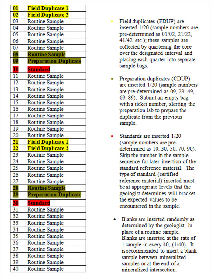
Figure 10.1: Quality Control/Quality Assurance
procedures instituted by Cardero for all drill
core sampled from the
Longnose property
Field duplicates (FDUP) in this case refer to ¼ core duplicates of the same sampling interval. A preparation duplicate (CDUP) consists of a poly bag containing only a sample tag with instructions for laboratory personnel to prepare the sample from the preceding standard drill core analysis by taking a split after the coarse crushing stage.
Three different reference materials were used in the sampling program at Titac. “TTC-1” and “LNC-1”, which are in-house reference materials created by Cardero; and “SX67-05” which is a certified reference materials manufactured for Brammer Standard Company, Inc. (14603 Benfer Road, Houston, Texas 77069, United States of America) by accredited laboratory Dillinger Hutte Laboratory (GAZ; Association for the Accreditation and Certification GmbH, Attestation no. 91021).
Blank material is collected locally in Minnesota from bedrock outcroppings of the Pokegama quartzite near Virginia, Minnesota. Pokegama quartzite is a suitable blank reference because it is dominantly composed of SiO2.
| DJF_MJ/WB | Titac-NI43-101Rpt (4).docx | January 27, 2012 |
| 2CC031.004 – Cardero Resources | |
| Titac Project NI 43-101 | Page 52 |
| 10.8 |
SRK Comments |
|
In the opinion of SRK the sampling preparation, security and analytical procedures used by CIOUS are consistent with generally accepted industry best practices and are therefore adequate. |
| DJF_MJ/WB | Titac-NI43-101Rpt (4).docx | January 27, 2012 |
| 2CC031.004 – Cardero Resources | |
| Titac Project NI 43-101 | Page 53 |
| 11 |
Data Verification |
|
| |
| 11.1 |
Quality Control Results |
|
| |
|
Quality control samples (duplicates, blanks and standards) are used to monitor laboratory sample preparation, potential for contamination and analytical accuracy. | |
|
| |
|
A total of 308 reference materials and 146 Pokegama quartzite blank samples were submitted blindly to the laboratory during the core sampling campaign at Titac in 2010 and 2011. A total of 316 quarter core duplicate pairs were collected and submitted to the laboratory and 305 preparation duplicate pairs were prepared by the laboratory. Only the quarter core duplicates were blind to the laboratory. All analytical data including quality control samples were checked and verified by Cardero’s senior geochemist, Tansy O’Connor-Parsons and reviewed by SRK. | |
|
| |
|
Coarse blank samples (Figure 11.1) show a slightly higher than background value for TiO2 , indicating that the blank is not devoid of titanium. SRK normally compares the blank data to five times the detection limit, in this case a value of 0.05 % TiO2 however this blank has an average TiO2 value 10 times the detection limit. When the individual values are compared to a low baseline value of 0.1% TiO2 the blank sample results indicate low-level carryover contamination during the preparation through to analytical stage. |
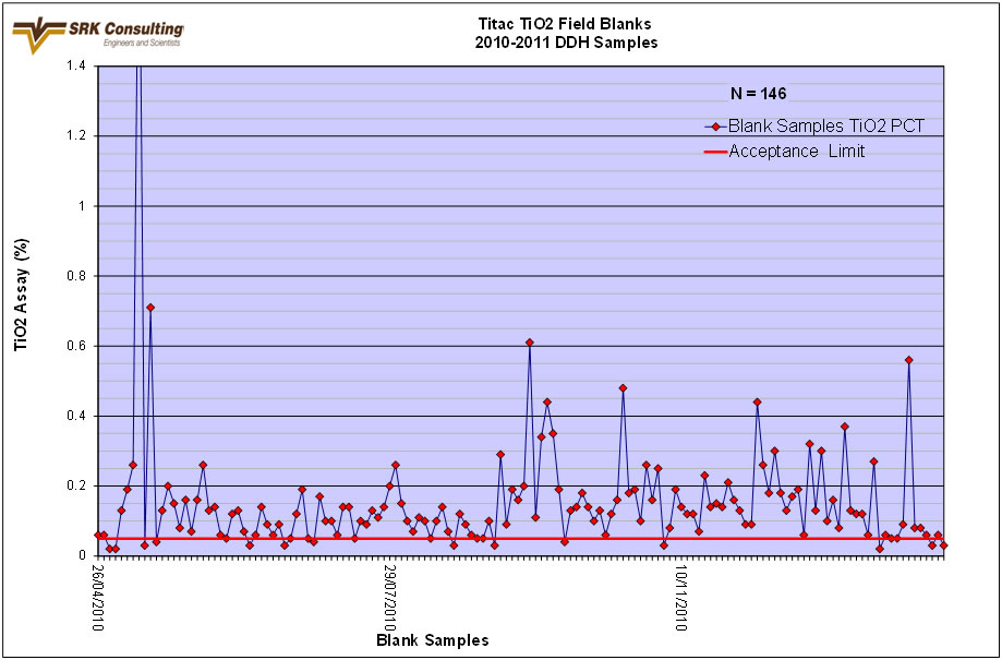
Figure 11.1: Blank analytical results over time for Pokegama Quartzite Blank samples submitted with Titac deposit samples
Scatter plots, percent relative difference plots and percentile rank charts for quarter-core duplicate titanium data are presented in Figures 11.2, 11.3 and 11.4 respectively. Good correlation is seen between quarter-core duplicate samples with 94% of duplicate pairs having a half absolute relative difference of less than 10%.
| DJF_MJ/WB | Titac-NI43-101Rpt (4).docx | January 27, 2012 |
| 2CC031.004 – Cardero Resources | |
| Titac Project NI 43-101 | Page 54 |
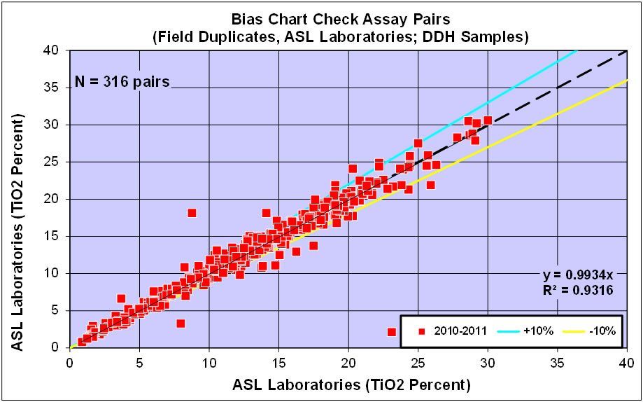
Figure 11.2: Scatterplot graph of TiO2 data for quarter core field duplicates for the Titac Project
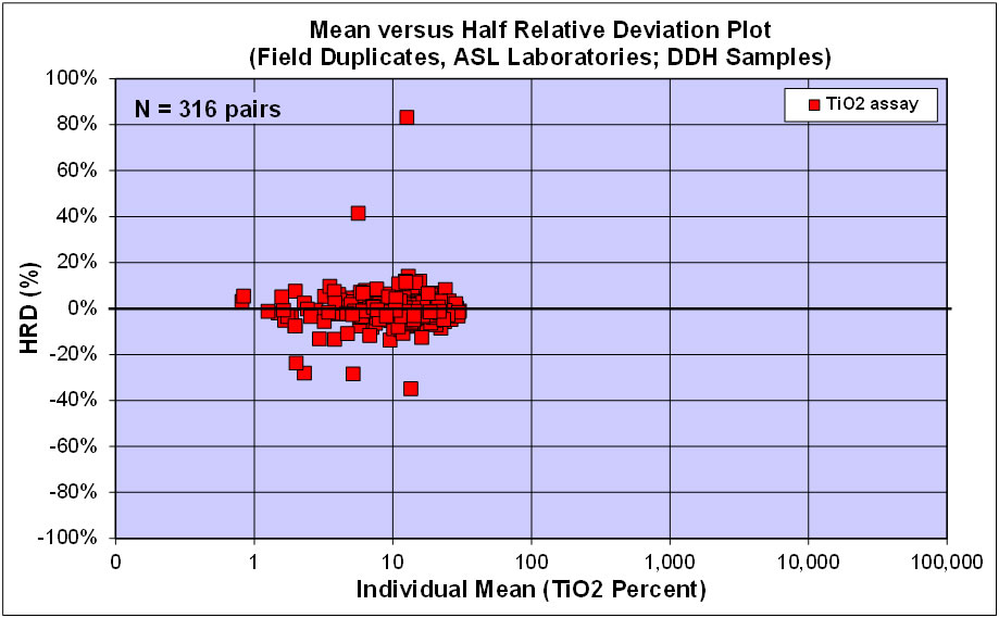
Figure 11.3: Half Relative Deviation Plot of TiO2 data for quarter core field duplicates for the Titac Project
| DJF_MJ/WB | Titac-NI43-101Rpt (4).docx | January 27, 2012 |
| 2CC031.004 – Cardero Resources | |
| Titac Project NI 43-101 | Page 55 |

Figure 11.4: Ranked Half Absolute Relative Deviation Plot of TiO2 data for quarter core field duplicates for the Titac Project
Scatter plots, percent relative difference plots and percentile rank charts for preparation duplicate titanium data are presented in Figures 11.5, 11.6 and 11.7 respectively. Excellent correlation is seen between preparation duplicate samples with 97.7% of duplicate pairs having a half absolute relative difference of less than 10%.
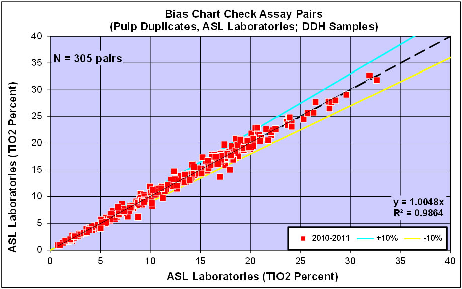
Figure 11.5:Scatterplot graph of TiO2 data for preparation duplicates for the Titac Project
| DJF_MJ/WB | Titac-NI43-101Rpt (4).docx | January 27, 2012 |
| 2CC031.004 – Cardero Resources | |
| Titac Project NI 43-101 | Page 56 |
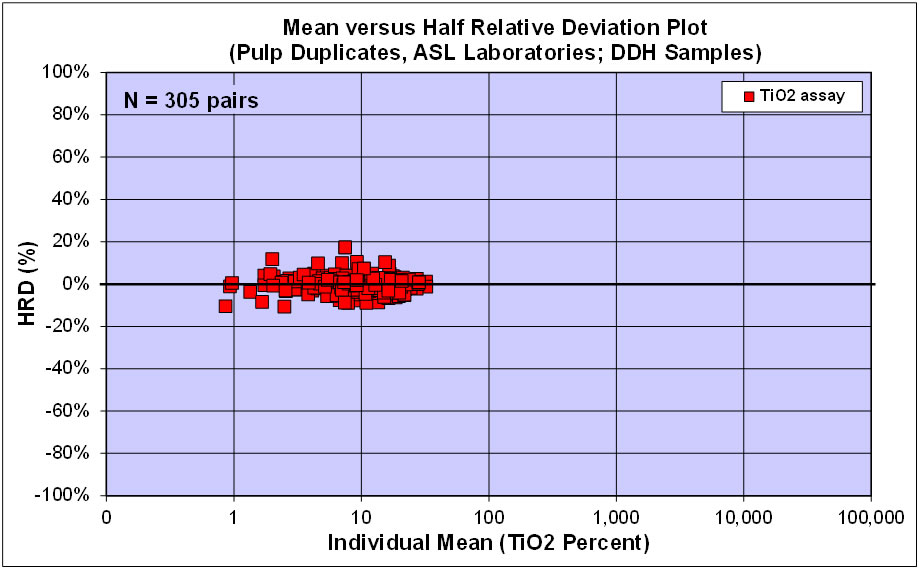
Figure 11.6: Half Relative Deviation Plot of TiO2 data for preparation duplicates for the Titac Project
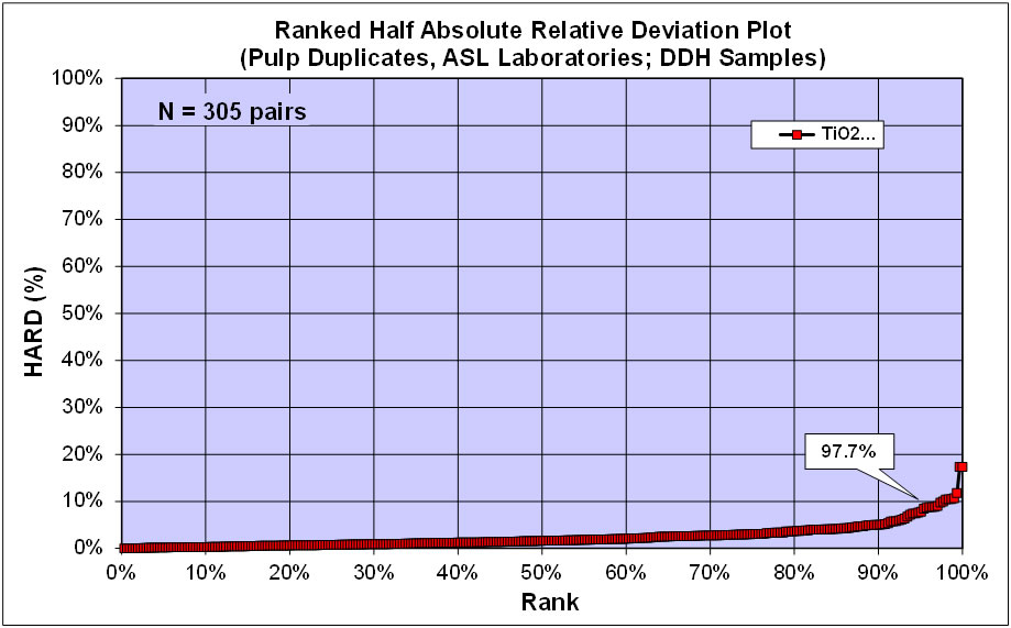
Figure 11.7: Ranked Half Absolute Relative Deviation Plot of TiO2 data for preparation duplicates for the Titac Project
| DJF_MJ/WB | Titac-NI43-101Rpt (4).docx | January 27, 2012 |
| 2CC031.004 – Cardero Resources | |
| Titac Project NI 43-101 | Page 57 |
Two internal reference materials (LNC-1 and TTC-1) and one commercial standard reference material (SX67-05) were utilized by CIOUS. Reference material results are plotted against their known TiO2 concentration with tolerance levels within 10% (Figures 11.8, 11.9 and 11.10) .
A number of results for LNC-1 reported TiO2 values similar to the average TiO2 value for internal reference material TTC-1. The corresponding Fe2O3 values reported for these samples were also representative of the expected Fe2O3 values for TTC-1. In these cases, the reference materials have been mislabelled. One result for LNC-1 is clearly more in line with a blank sample, again a case of mislabelling of control samples. TTC-1 shows a slightly high bias and relatively large scatter. A slight negative bias for some SX6705 samples were noted at the beginning of the program, however re-analysis of the reference material and surrounding samples resulted in comparable results.
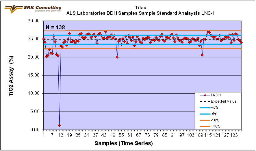
Figure 11.8: Internal reference material LNC-1 performance for TiO2
| DJF_MJ/WB | Titac-NI43-101Rpt (4).docx | January 27, 2012 |
| 2CC031.004 – Cardero Resources | |
| Titac Project NI 43-101 | Page 58 |
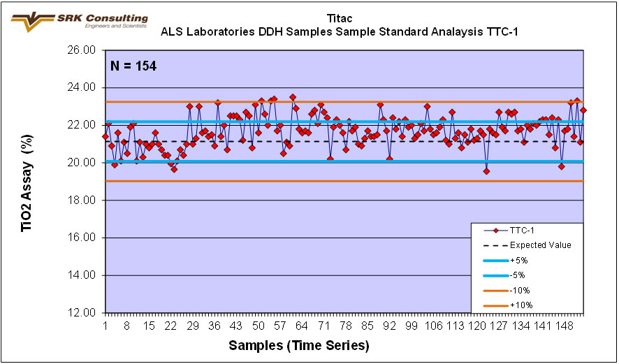
Figure 11.9: Internal reference material TTC-1 performance for TiO2
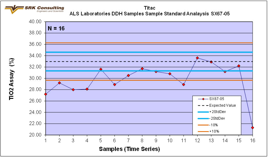
Figure 11.10: Standard reference material SX67-05 performance for TiO2
To monitor the analytical accuracy of the laboratory, umpire/check assays were submitted to a second laboratory (Acme Analytical Laboratories in Vancouver, BC) where the sample pulps were analysed by the 4A04 package (lithium metaborate fusion/ICP-ES finish). All 303 samples from a single drill hole (TTC-019) were submitted for the umpire assay, as the drill hole intersected all levels of ferro-titanium mineralization. The results for TiO2 and Fe2O3 are presented in Figure 11.11. The data correlate very well for both analytes, however there is a slight low bias at the concentrations of > 27% TiO2 for the data from the ALS Minerals laboratory. This is not considered to be significant, as the data is within 10% analytical precision.
| DJF_MJ/WB | Titac-NI43-101Rpt (4).docx | January 27, 2012 |
| 2CC031.004 – Cardero Resources | |
| Titac Project NI 43-101 | Page 59 |
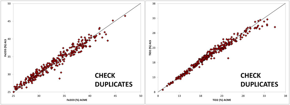
Figure 11.8: Scatterplots presenting analytical umpire
(check) assays versus original assay
results for Fe2O3 (left) and TiO2 (right)
data
|
SRK has reviewed the results of all QA/QC samples. Duplicate and umpire analysis performed very well and blank samples performed adequately. The results of analytical standards are less ideal. Both internal standard results showed a large amount of scatter and standard TTC-1 showed a slight high bias. In addition, CIOUS did not complete full round robin testing on the standards, making them difficult to properly use as a reference. CIOUS should more carefully scrutinize analytical standards selection and standard results for future programs. If internal reference materials are to be used, these should be submitted to various laboratories to establish an average value and standard deviation for these materials. | |
|
In the opinion of SRK the results of the analytical QA/QC program used by CIOUS provide sufficient support that the analytical data is viable to support the exploration analysis and the Mineral Resource. | |
| 11.2 |
Veerifications by Cardero |
|
Cardero completed several processes to verify the exploration data that has been captured at the Project. | |
|
Firstly, all exploration data was entered into a database which provided a level of data checking to ensure that errors are minimized. This includes standardized naming conventions and limits on field entries. | |
|
Secondly, all paper records logging records were retained by Cardero and spot checks were made by Cardero head office staff to ensure that the database accurately reflected the data captured. Data from the site database is backed up weekly to Cardero’s Vancouver office server. | |
| 11.3 |
Veerifications by SRK |
|
SRK completed a series of verifications to ensure that the exploration data is reliable enough for the creation of the Mineral Resource. These verifications included the site visits review of field procedures, reviewing analytical quality control data, independent sampling and independent verification of the assay results. |
| DJF_MJ/WB | Titac-NI43-101Rpt (4).docx | January 27, 2012 |
| 2CC031.004 – Cardero Resources | |
| Titac Project NI 43-101 | Page 60 |
| 11.3.1 |
Site Visit |
|
During the site visit completed on March 12 and 13 2010, SRK was able to verify: |
| • | Exploration planning; | |
| • | Selection of drill hole sites; | |
| • | Mobilization of drill rigs; | |
| • | Drilling processes and drill rig core handling; | |
| • | Down-hole surveying; | |
| • | Collar site marking and surveying; | |
| • | Core logging; | |
| • | Core sampling; | |
| • | Sample QA/QC insertion; | |
| • | Sample shipping and security; and | |
| • | Data capture and backup. |
|
In the opinion of SRK the site procedures used by CIOUS are consistent with generally accepted industry best practices and are therefore adequate. | |
| 11.3.2 |
Verifications of Analytical Quality Control Data |
|
Table 11.1 summarizes CIOUS’s insertion rate for analytical QA/QC samples. |
Table 11.1: Summary of Analytical Quality Control Data Produced By Cardero on the Project, 2010/11
| Quality Control Samples |
Drilling and Sampling Programs |
Percent of Samples (%) |
Comment |
| Sample Count | 4943 | ||
| Field Blanks | 146 | 3.0% | Locally derived quartzite material |
| Standards | 308 | 6.2% | |
| TTC-1 | 154 | 3.1% | Internal Cardero reference material |
| LNC-1 | 138 | 2.8% | Internal Cardero reference material |
| SX67-05 | 16 | 0.3% | Certified Commercial Standard, Brammer |
| Field Duplicates | 316 | 6.4% | Quarter Core |
| Preparation Duplicates | 305 | 6.2% | Split of course crush |
| Total QC Samples | 5421 | 109.7% |
| 11.3.3 |
Independent Verification Sampling |
|
During the SRK site visits, two independent verification samples were collected from the Titac deposit and sent to ALS for processing. The results are shown in Table 11-2. Even though only two samples were collected, the samples showed very good correlation between the original Cardero TiO2 and Fe2O3 assays, and the independent duplicate results. |
| DJF_MJ/WB | Titac-NI43-101Rpt (4).docx | January 27, 2012 |
| 2CC031.004 – Cardero Resources | |
| Titac Project NI 43-101 | Page 61 |
Table 11.2: Assay Results for Verification Samples Collected SRK on the Titac Project
Hole ID |
From (m) |
To (m) |
Original TiO2 (%) |
SRK Duplicate TiO2 (%) |
Original Fe2O3 (%) |
SRK Duplicate Fe2O3 (%) |
| TTC-003-2010 | 35.36 | 36.88 | 11.4 | 12.05 | 38.5 | 38.6 |
| TTC-003-2010 | 36.88 | 38.41 | 13.25 | 14.55 | 44.4 | 43.4 |
| 11.3.4 |
Independent Assay Verification |
|
SRK independently verified a hundred percent of the assay results by downloading the assay certificates directly from the laboratory and comparing the compiled results in an Access database. SRK found no errors in the TiO2 and Fe2 O3 analytical data. |
| DJF_MJ/WB | Titac-NI43-101Rpt (4).docx | January 27, 2012 |
| 2CC031.004 – Cardero Resources | |
| Titac Project NI 43-101 | Page 62 |
| 12 |
Mineral Processing and Metallurgical Testing |
|
Relatively little metallurgical test work has been completed on the Titac deposits. What has been completed can be divided into historic work completed before Cardero’s involvement in the property and current work completed more recently by Cardero. | |
|
Historically, significant amounts of historical beneficiation work was completed on other OUI deposits such as Longnose deposit, another OUI body 40k north of Titac. This work was largely conducted by the Coleraine Minerals Research Lab (“CMRL”) which is part of the University of Minnesota Duluth’s (UMD’s) Natural Resources Research Institute (NRRI), located in Coleraine, Minnesota, USA. The work pre-dates the NI 43-101 standards however the work was completed to high standards and will be useful in designing the future beneficiation work. | |
|
A description of the historic metallurgical work is contained within Section 5. |
| 12.1 | Recent Metallurgical Testwork |
|
Since Cardero’s involvement in the project, little metallurgical analysis has been completed by Cardero. However, in December 2011, Davis Tube tests were completed in order to determine the proportion of magnetic material and the value of Fe within the magnetic concentrate. At this time, only preliminary results of these tests have been received. | |
|
| |
|
Approximately 347 samples from 2010 and 2011 Titac drill holes were selected for Davies Tube processing. Davies Tube tests utilize an electromagnet to separate material into magnetic and non- magnetic/para-magnetic material. Samples were selected to cover a wide range of grades as well as being spatially representative. Analytical pulp rejects were utilized for the tests which were completed at G&T Metallurgical (G&T) in Kamloops BC. | |
|
| |
|
At G&T each sample was assayed for Fe% (direct Fe% analysis as opposed to Fe2 O3 that was completed in the main assay work). Then 10 g or 30 g of the material was selected for the tests. This material was pulp reject material (pulverized to 80% passing 200 mesh) and was not further re- crushed in any way by G&T. The material was separated into a magnetic and non-magnetic fraction by passing over a magnet set at 3000 gauss. The magnetic fraction was then weighed and the magnetic concentrate re-assayed for Fe%. | |
|
| |
|
A total of 301 of these samples were from the Titac mineralization domains, with the remainder falling outside the modelled domains. | |
|
| |
|
In a deposit with magnetite as the dominant Fe bearing mineral, this test provides data to calculate a regression of the proportion of magnetite expected at a range of Fe grades and the conversion of the Fe2 O3 or Fe% analysis into a magnetite estimate. However, due to the fact that Fe partitions into ilmenite and a small but unknown amount of ilmenite would have partitioned into the magnetic concentrate, further work must be performed to properly quantify the magnetite content of these samples. A mineralogical study of a subset of these samples and concentrates would assist with determining the amount of ilmenite in the concentrate and TiO2 assays of the concentrate would allow for determination of the titaniferous magnetite as well. | |
|
| |
|
The Davis Tube tests were not utilized in the definition of the Mineral Resource as accurately quantifying magnetite is not possible until further mineralogical work is completed. |
| DJF_MJ/WB | Titac-NI43-101Rpt (4).docx | January 27, 2012 |
| 2CC031.004 – Cardero Resources | |
| Titac Project NI 43-101 | Page 63 |
| 13 |
Mineral Resource Estimates |
| 13.1 |
Introduction |
|
The Mineral Resource Statement presented herein represents the first Mineral Resource evaluation prepared for the Project in accordance with the Canadian Securities Administrators’ NI 43-101. | |
|
The Mineral Resource model prepared by SRK considers 23 core boreholes drilled by CIOUS during 2010 and 2011. The resource estimation work was completed by Darrell Farrow, Pr. Sci. Nat. under the supervision of Mike Johnson, P.Geo. who is responsible for the resource. By virtue of their education, membership to a recognized professional association and relevant work experience, Darrell Farrow and Mike Johnson are independent Qualified Persons as this term is defined by NI 43-101. The effective date of the resource statement is January 19, 2012. | |
|
This section describes the resource estimation methodology and summarizes the key assumptions considered by SRK. In the opinion of SRK, the resource evaluation reported herein is a reasonable representation of the global TiO2 and Fe2 O3 mineral resources found in the Titac South deposit of the Project at the current level of sampling. The mineral resources have been estimated in conformity with generally accepted CIM “Estimation of Mineral Resource and Mineral Reserves Best Practices” guidelines and are reported in accordance with the Canadian Securities Administrators’ NI 43-101. Mineral resources are not mineral reserves and do not have demonstrated economic viability. There is no certainty that all or any part of the mineral resource will be converted into mineral reserve. | |
|
The database used to estimate the Project mineral resources was audited by SRK. SRK is of the opinion that the current drilling information is sufficiently reliable to interpret with reasonable confidence the boundaries for ilmenite and magnetite mineralization and that the assay data are sufficiently reliable to support mineral resource estimation. | |
|
Gemcom Gems version 6.3.1 was used to construct the geological solids, prepare assay data for geostatistical analysis, construct the block model, estimate metal grades and tabulate mineral resources. The Geostatistical Software Library (“GSLib”) family of software were used for geostatistical analysis. Gems was used for the variography analysis. | |
| 13.2 |
Resource Estimation Procedures |
|
The resource evaluation methodology involved the following procedures: |
| • | Database compilation and verification; | |
| • | Construction of wireframe models for the boundaries of the oxide mineralization in Titac South; | |
| • | Definition of resource domains; | |
| • | Data conditioning (compositing and capping) for geostatistical analysis and variography; | |
| • | Block modelling and grade interpolation; | |
| • | Resource classification and validation; | |
| • | Assessment of “reasonable prospects for economic extraction” and selection of appropriate cut- off grades; and | |
| • | Preparation of the Mineral Resource Statement. |
| 13.3 |
Resource Database |
|
SRK audited and reviewed data provided by Cardero to create a Gems database from which the Mineral Resource estimation was based. The database includes the following tables: |
| • | Drill hole collar information such as location and length; | |
| • | Down hole survey information such as direction and dip; |
| DJF_MJ/WB | Titac-NI43-101Rpt (4).docx | January 27, 2012 |
| 2CC031.004 – Cardero Resources | |
| Titac Project NI 43-101 | Page 64 |
| • | Lithology information including rock group codes and interpreted geology; | |
| • | Down hole magnetic susceptibility data; | |
| • | Down hole specific gravity measurements ; and, | |
| • | Chemical analytical (assay) records. |
The data encompassed 32 drill holes, 1754 down hole survey readings, 4943 TiO2 and Fe2O3 assays, and 1746 specific gravity measurements of which 24 drill holes, 1322 down hole survey readings, 3929 TiO2 and Fe2O3 assays and 1326 specific gravity measurements pertain to the Titac South deposit (Table 13.1) .
Basic statistics of for the drill hole assay and specific gravity data for Titac South are presented in Tables 13.2 and 13.3.
Table 13.1: Summary of Titac drill hole data
| Titac North | Titac South | Total | |
| Drill Holes | 8 | 24 | 32 |
| Down Hole Survey | 432 | 1322 | 1754 |
| Assays | 1014 | 3929 | 4943 |
| Specific Gravity | 420 | 1326 | 1746 |
Table 13.2: Statistical Summary of Database Assay Results for Titac South
| TiO2 | Fe2O3 | Length | |
| Count | 3929 | ||
| Minimum | 0.47 | 2.45 | 0.2 |
| Maximum | 36.80 | 64.40 | 3.6 |
| Mean | 13.60 | 27.49 | 1.6 |
| Standard Deviation | 6.67 | 9.48 | 0.3 |
Table 13.3: Statistical Summary of Database Specific Gravity Results for Titac South
| SG | |
| Count | 1326 |
| Minimum | 2.27 |
| Maximum | 4.82 |
| Mean | 3.43 |
| Standard Deviation | 0.39 |
| 13.4 |
Solid Body Modelling |
|
Solid models were created to provide spatial limits for each of the mineralization domains within the Titac South Deposit. Drilling on Titac North was deemed to be insufficient to create a reliable solids model. | |
|
Domains were created by interpretation of the drill hole lithology data from the 2010 and 2011 drill holes. The domains were broadly defined based upon the designation of drill core intervals as peridotite or pyroxenite dominated oxide bearing ultramafic rocks. A marginal zone of mixed peridotite, pyroxenite and country rock was also modeled. The pyroxenite and peridotite domains predominantly contain pyroxenite and peridotite material respectively, however shorter intervals of other rock types do occur within these modeled domains. |
| DJF_MJ/WB | Titac-NI43-101Rpt (4).docx | January 27, 2012 |
| 2CC031.004 – Cardero Resources | |
| Titac Project NI 43-101 | Page 65 |
Gemcom’s GemsTM 6.3.1 software was used to create the wireframes and the boundaries were limited to the overburden surface. Topographic and overburden surfaces were modeled from drill hole data. These surfaces were used to code the appropriate portions of the block model as air or overburden.
Figure 13.1 and 13.2 show the interpreted domains in plan and three dimensional view respectively.
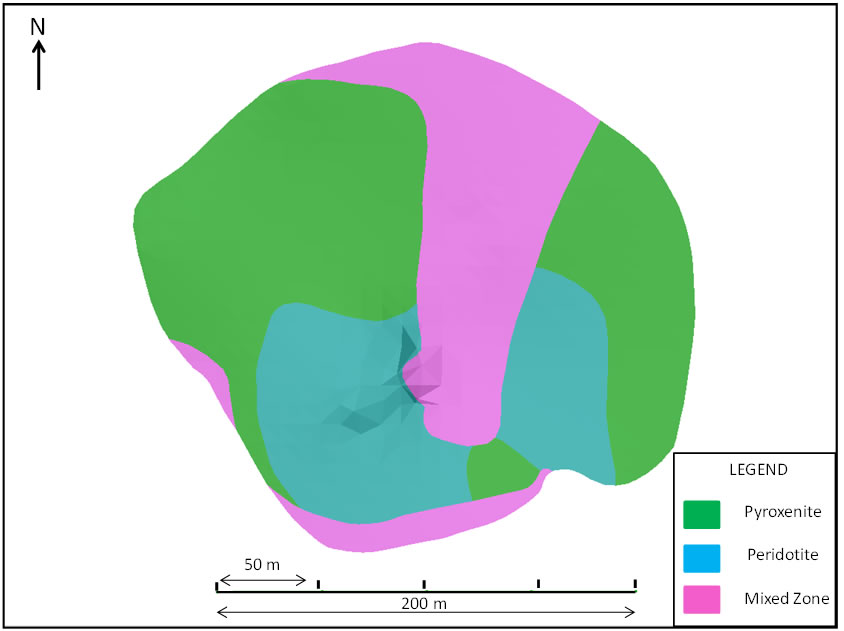
Figure 13.1 Titac South Plan View of modeled domains
| DJF_MJ/WB | Titac-NI43-101Rpt (4).docx | January 27, 2012 |
| 2CC031.004 – Cardero Resources | |
| Titac Project NI 43-101 | Page 66 |
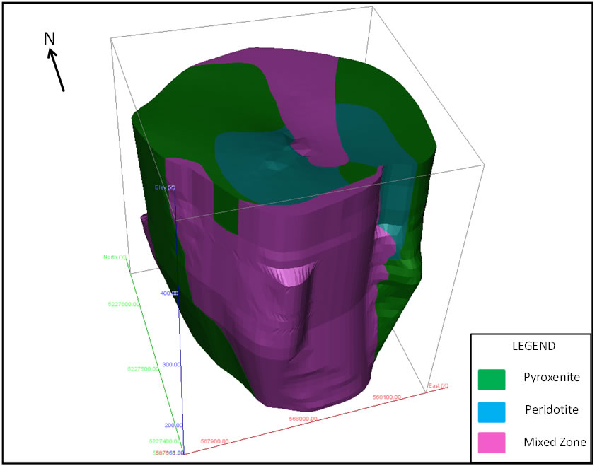
Figure 13.2 Titac South 3-D model domains
| 13.5 | Specific Gravity |
|
The data supplied by Cardero for Titac South included a total of 1326 specific gravity measurements on core samples, 855 of which fall within the modelled solids. Specific gravity was measured on core samples by CIOUS using a laboratory scale and recording the mass of drill hole core pieces in air and water. Drill hole core was not sealed prior to immersion, however porosity is not likely to be an issue with this type of rock. No strong correlation between specific gravity measurements and TiO2 or Fe2 O3 assay results was noted. | |
|
| |
| 13.6 |
Compositing |
|
| |
|
A total of 2837 diamond drill hole assay intervals fall within the modelled solids for Titac South. Drill hole assay sample lengths are summarized in Figure 13.3 which is a histogram of sample lengths. Approximately 75 % of samples are less than 1.8 m in length and therefore a compositing interval of 1.8 m was selected. | |
|
| |
|
The assays were imported into Gems and composited to 1.8 m length weighted intervals within the modeled domains. |
| DJF_MJ/WB | Titac-NI43-101Rpt (4).docx | January 27, 2012 |
| 2CC031.004 – Cardero Resources | |
| Titac Project NI 43-101 | Page 67 |
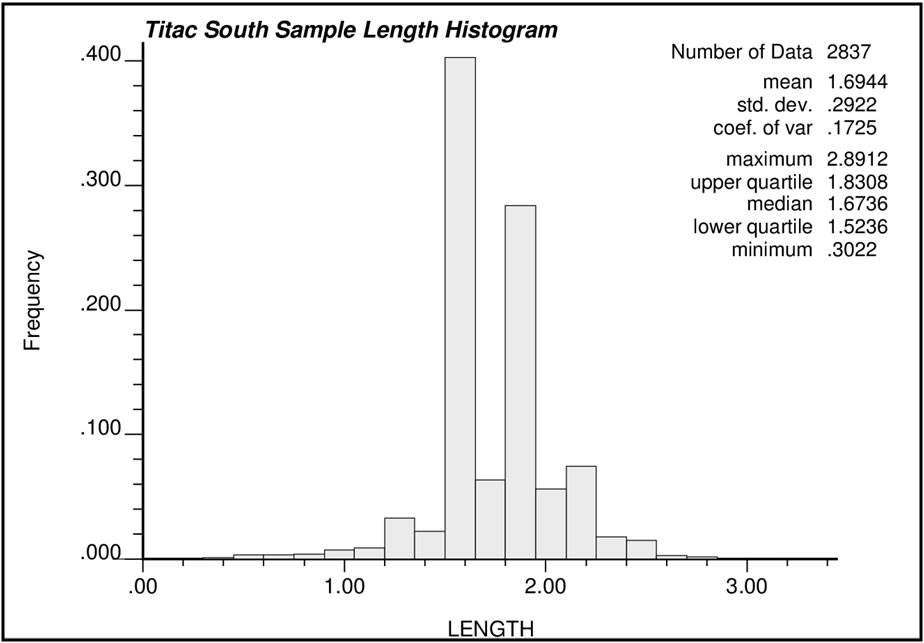
|
Figure 13.3 Histogram of Sample Lengths | |
| 13.7 |
Capping |
|
Block grade estimates may be unduly affected by high grade outliers. Before compositing, grade capping analysis was conducted on the domain-coded sample assay data in order to limit the influence of extreme assay values during estimation. The assays from the modeled pyroxenite, peridotie and mixed domains were separately examined using histograms, and cumulative frequency plots. SRK determined that capping was unnecessary for both TiO2 and Fe2 O3 in all three domains. | |
| 13.8 |
Statistical Analysis and Variography |
| 13.8.1 |
Sample and Composite Statistics |
|
Composite statistics for TiO2 and Fe2 03 as well as sample statistics for specific gravity are described below. | |
|
TiO2 Composites Statistics | |
|
Figures 13.4, 13.5 and 13.6 show the histograms of the TiO2 composites within the pyroxenite, peridotie and mixed domains respectively, as well as the basic statistics of each. The average peridotite TiO2 value is 17.63%, while the average in the pyroxenite is 16.41%. The average TiO2 value for the mixed domain is 9.64%. |
| DJF_MJ/WB | Titac-NI43-101Rpt (4).docx | January 27, 2012 |
| 2CC031.004 – Cardero Resources | |
| Titac Project NI 43-101 | Page 68 |
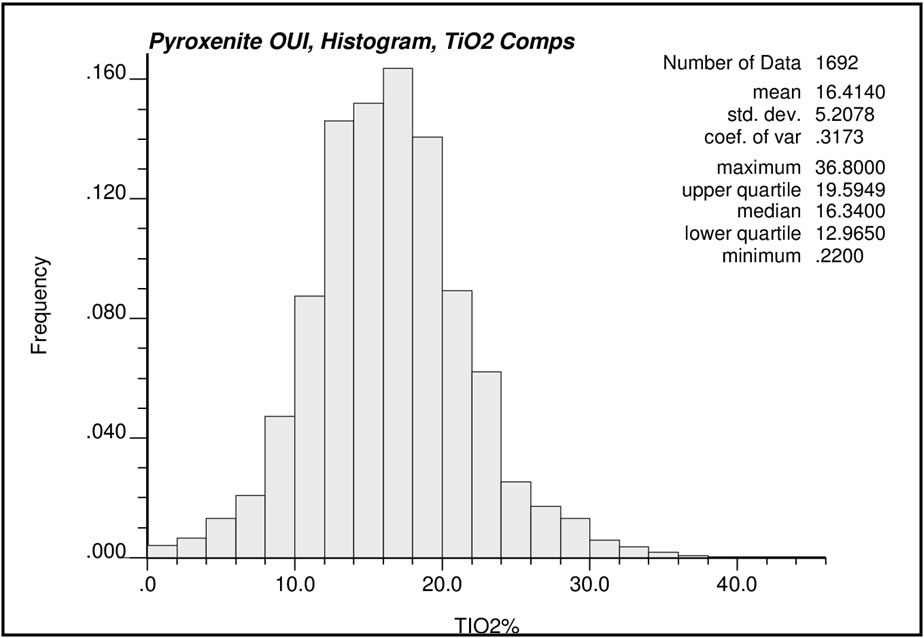
Figure 13.4: Histogram of composite TiO2 Assay samples within the Pyroxenite Domain.
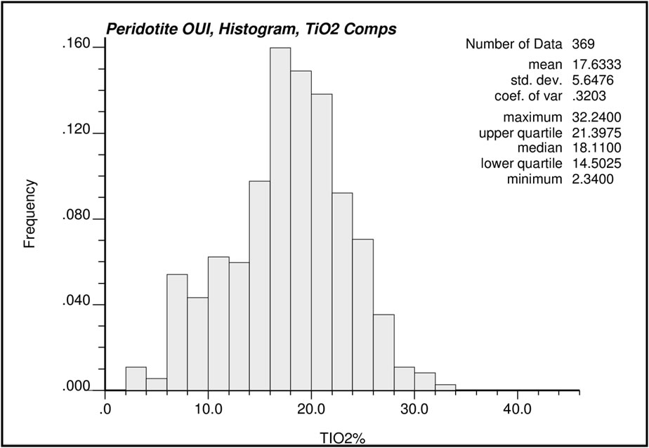
Figure 13.5: Histogram of composite TiO2 Assay samples within the Peridotite Domain.
| DJF_MJ/WB | Titac-NI43-101Rpt (4).docx | January 27, 2012 |
| 2CC031.004 – Cardero Resources | |
| Titac Project NI 43-101 | Page 69 |
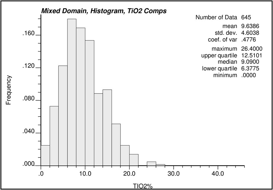
Figure 13.6: Histogram of composite TiO2 Assay samples within the Mixed Domain Fe2O3 Composites Statistics
Histograms of the Fe2O3 composites within each domain, as well as the basic statistics of each are shown in Figures 13.7, 13.8 and 13.9. The average peridotite Fe2O3 value is 36.26%, while the average in the pyroxenite is 30.58% . The average Fe2O3 value for the mixed domain is 23.69% .
| DJF_MJ/WB | Titac-NI43-101Rpt (4).docx | January 27, 2012 |
| 2CC031.004 – Cardero Resources | |
| Titac Project NI 43-101 | Page 70 |
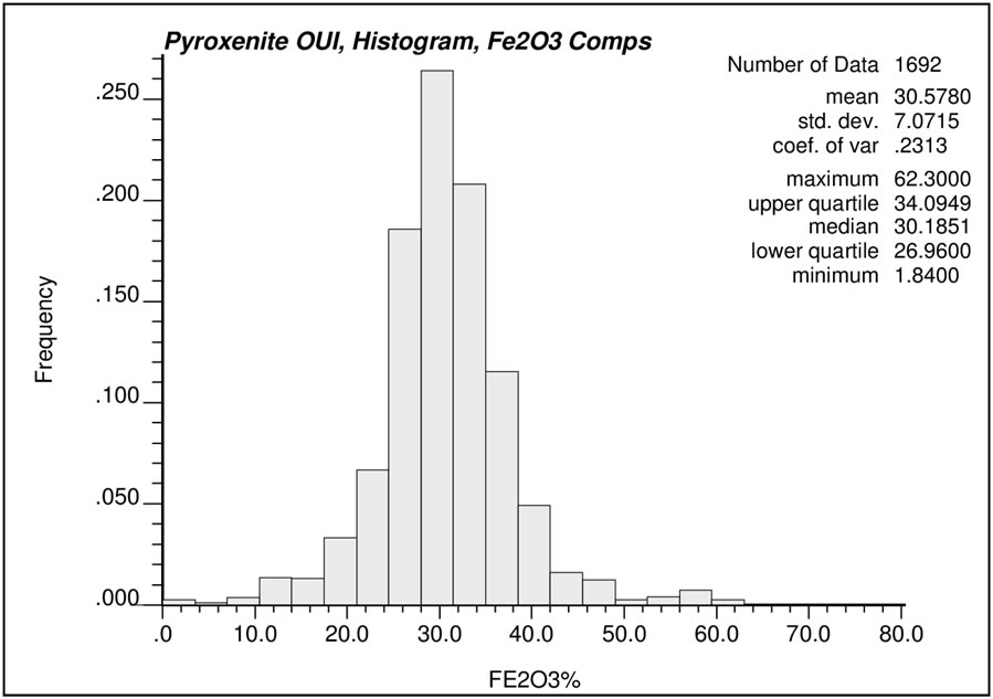
Figure 13.7: Histogram of composite Fe2O3 Assay samples within the Pyroxenite Domain

Figure 13.8:Histogram of composite Fe2O3 Assay samples within the Peridotite Domain
| DJF_MJ/WB | Titac-NI43-101Rpt (4).docx | January 27, 2012 |
| 2CC031.004 – Cardero Resources | |
| Titac Project NI 43-101 | Page 71 |
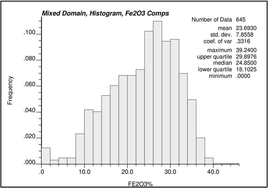
Figure 13.9: Histogram of composite Fe2O3 Assay samples within the Mixed Domain
| 13.8.2 | Variography |
|
Experimental semi-variograms were generated for TiO2 from composite grade data for the pyroxenite oxide bearing ultramafic rocks. The nugget effect was established from a down hole linear semi- variogram. Modeled directions of spatial continuity were identified with a principle azimuth of 120 °and principle dip of 65°. Two spherical structures were modeled with rotation defined by the Gems azimuth, dip, azimuth convention within the block model coordinate space. The continuity ellipsoid was displayed as a search ellipsoid in Gems to validate the ellipsoid orientation. Due to limited data for the peridotite and mixed domains, experimental semi-variograms could not be generated for TiO2 and Fe2 O3 from composite grade data for these domains. Experimental semi-variograms could not be generated for Fe2 O3 from composite grade data for the pyroxenite domain. | |
|
| |
|
The semi-variogram model used for TiO2 and Fe2 O2 grade estimation within the pyroxenite, peridotite and mixed domains (Figure 13.10) is summarized in Table 13.5. |
| DJF_MJ/WB | Titac-NI43-101Rpt (4).docx | January 27, 2012 |
| 2CC031.004 – Cardero Resources | |
| Titac Project NI 43-101 | Page 72 |
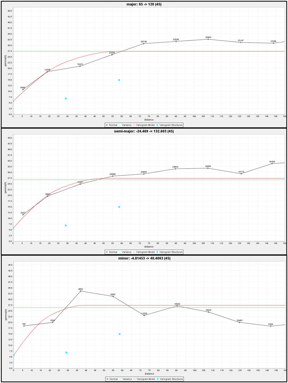
Figure 13.10: Modelled directional and down hole semi-variograms for the Pyroxenite Domain
| DJF_MJ/WB | Titac-NI43-101Rpt (4).docx | January 27, 2012 |
| 2CC031.004 – Cardero Resources | |
| Titac Project NI 43-101 | Page 73 |
| 13.9 | Block Model and Grade Estimation |
|
A block model was constructed to cover the entire extent of the modeled mineralized domains for Titac South. The block model includes separate sub-models for TiO2 and Fe2 O3 grade estimates as well as estimated specific gravity and validation estimates. A block percentage model was used to accurately determine volume and tonnage values based on the modelled wireframes. The geometrical parameters of the block model are summarized in Table 13.4 | |
| Table 13.4: Block model location and setup |
| Description | Easting (X) | Northing (Y) | Elevation (Z) |
| Block Model Origin NAD 83 | 567500 | 5227000 | 500 |
| Block Dimensions (metres) | 10 | 10 | 10 |
| Number of Blocks | 100 | 100 | 40 |
| Rotation (degree) | 0° |
| 13.9.1 |
Grade Interpolation |
|
Ordinary Kriging (“OK”) of composite values was used for the estimation of block grades. For TiO2 and Fe2 O3 , a two pass series of expanding ellipsoids was used for sample selection and estimation with the primary and secondary axes of the search ellipsoid defined by the semi-variogram ranges. Successive passes only calculate grades into blocks that have not been interpolated by the previous passes. The semi-variogram and continuity ellipsoids generated for TiO2 for the pyroxenite domain were used to estimate Fe2 O3 grades for the pyroxenite domain and TiO2 and Fe2 O3 grades for both the peridotite and mixed domains. | |
|
Composite data used for estimation was restricted to samples located within the respective domains. Estimation criteria for the pyroxenite, peridotite and mixed domains are summarized in Table 13.6. All interpolated blocks were classified as Inferred Mineral Resource. | |
| 13.9.2 |
Specific Gravity Interpolation |
|
Block density data was interpolated from specific gravity point measurements using the inverse distance squared (ID2) method. A two pass series of expanding ellipsoids was used for sample selection and estimation. Specific gravity data used in the interpolation was restricted to samples located within the respective domains. Specific gravity interpolation criteria for all Titac South modelled domains are summarized in Table 13.7. | |
|
Country rock blocks were assigned an average density value of 2.93 g/cm3 and overburden blocks were assigned an average density value of 2.0 g/cm3 . |
| 13.10 | Model Validation |
|
The block model was validated visually by the inspection of successive section lines in order to confirm that the block model correctly reflects the distribution of high-grade and low-grade samples. An inverse distance squared estimate (“ID2”) was prepared for the blocks using the same search criteria and compared against the OK estimate. The average composite sample grades for all blocks containing composite samples were compared to the OK and ID2 estimates using scatter plots. The scatter plots for TiO2 and Fe2 O3 within each of the pyroxenite, peridotite and mixed domains are shown in Figures 13.11, 13.13 and 13.13 respectively. | |
|
Good correlation between OK, ID2 and average composite sample grades was observed for both TiO2 and Fe2 O3 grades in the pyroxenite and peridotite domains. |
| DJF_MJ/WB | Titac-NI43-101Rpt (4).docx | January 27, 2012 |
| 2CC031.004 – Cardero Resources | |
| Titac Project NI 43-101 | Page 74 |
In the mixed zone, good correlation between OK and ID2 was observed for both TiO2 and Fe2O3 grades as well as between OK and average composite sample grades for Fe2O3. However, greater scatter and slightly more smoothing was observed when comparing OK and average sample grades for TiO2 within the mixed zone (Figure 13.13).
| DJF_MJ/WB | Titac-NI43-101Rpt (4).docx | January 27, 2012 |
| 2CC031.004 – Cardero Resources | |
| Titac Project NI 43-101 | Page 75 |
Table 13.5: Modelled semi-variograms for Titac South Pyroxenite Domain
| Domain | Metal | Nugget C0 | Sill 1 | Sill 2 | Gems | Range 1 | Range 2 | ||||||
| Principal
Azimuth |
Principal
Dip |
Intermediate
Azimuth |
X- Rot |
Y- Rot |
Z- Rot |
X- Rot |
Y- Rot |
Z- Rot |
|||||
| Pyroxenite | TiO2 | 5.68 | 6.85 | 14.89 | 120 | 65 | 132.603 | 29 | 25 | 20 | 58 | 51 | 39 |
Table 13.6: Search ellipse parameters for Titac South Domains
| Commodity | Estimator | Search Pass |
Search Type |
Rotation | Search Ellipse Size | Number of Composites |
Max. Samples per DDH |
|||||
| Principal
Azimuth |
Principal
Dip |
Intermediate
Azimuth |
X (m) | Y (m) | Z (m) | Min. | Max. | |||||
| TiO2 | OK | 1 | Ellipsoidal | 120° | 65° | 132.6° | 60 | 50 | 40 | 6 | 16 | 4 |
| OK | 2 | Ellipsoidal | 120° | 65° | 132.6° | 250 | 150 | 150 | 6 | 16 | 4 | |
| Fe2O3 | OK | 1 | Ellipsoidal | 120° | 65° | 132.6° | 60 | 50 | 40 | 6 | 16 | 4 |
| OK | 2 | Ellipsoidal | 120° | 65° | 132.6° | 250 | 150 | 150 | 6 | 16 | 4 | |
Table 13.7: Search ellipse parameters for Titac South Domains
| Commodity | Estimator | Search
Pass |
Search
Type |
Rotation | Search Ellipse Size | Number of Composites | Max.
Samples per DDH |
|||||
| Principal
Azimuth |
Principal
Dip |
Intermediate
Azimuth |
X (m) | Y (m) | Z (m) | Min. | Max. | |||||
| SG | ID2 | 1 | Ellipsoidal | 120° | 65° | 132.6° | 60 | 50 | 40 | 6 | 16 | 4 |
| ID2 | 2 | Ellipsoidal | 120° | 65° | 132.6° | 250 | 150 | 150 | 6 | 16 | 4 | |
| DJF_MJ/WB | Titac-NI43-101Rpt (4).docx | January 27, 2012 |
| 2CC031.004 – Cardero Resources | |
| Titac Project NI 43-101 | Page 76 |

Figure 13.11: Scatter plots showing correlation
between OK, ID2 and average composite TiO2
and
Fe2O3 sample grades for Pyroxenite Domain
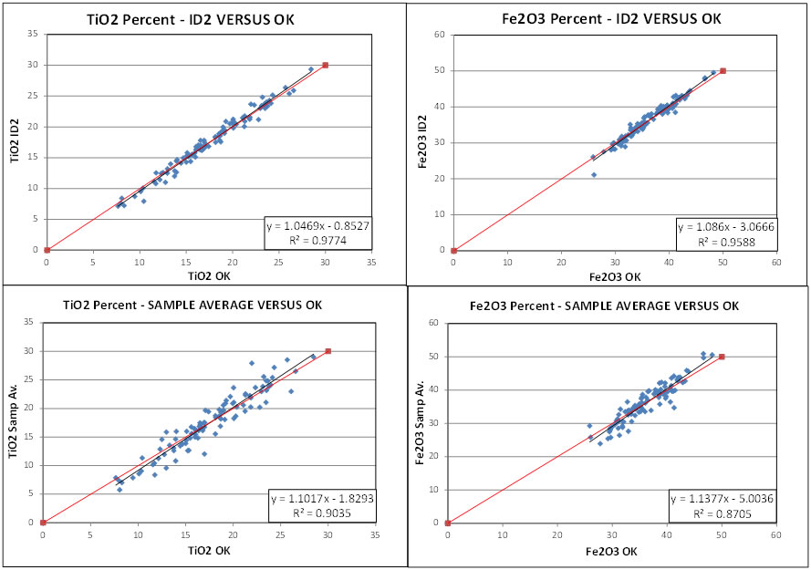
Figure 13.12: Scatter plots showing correlation
between OK, ID2 and average composite TiO2
and Fe2O3 sample grades for Peridotite Domain
| DJF_MJ/WB | Titac-NI43-101Rpt (4).docx | January 27, 2012 |
| 2CC031.004 – Cardero Resources | |
| Titac Project NI 43-101 | Page 77 |
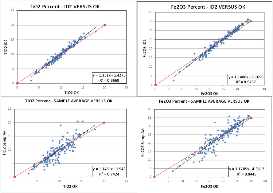
Figure 13.13: Scatter plots showing correlation
between OK, ID2 and average composite TiO2
and
Fe2O3 sample grades for Mixed Domain
| 13.11 |
Mineral Resource Classification |
|
Mineral resource classification is typically a subjective concept, industry best practices suggest that resource classification should consider both the confidence in the geological continuity of the mineralized structures, the quality and quantity of exploration data supporting the estimates and the geostatistical confidence in the tonnage and grade estimates. Appropriate classification criteria should aim at integrating both concepts to delineate regular areas at similar resource classification. | |
|
SRK is satisfied that the geological modelling honours the current geological information and knowledge. Although the drilling is good it is insufficient for a confident interpretation of the geological boundaries and mineralization. The location of the samples and the assay data are sufficiently reliable to support resource evaluation. The sampling information was acquired primarily by diamond core drilling of angled holes radiating from the centre of the Titac South deposit outwards with a few drill holes angled from the outside into the deposit. Due to the pipe like shape of the deposit, the drilling configuration and number of drill holes is not considered sufficient to delineate an Indicated Resource and all estimated blocks have been classified as Inferred. | |
| 13.12 |
Mineral Resource Statement |
|
CIM Definition Standards for Mineral Resources and Mineral Reserves (December 2005) defines a Mineral Resource as: | |
|
“(A) concentration or occurrence of diamonds, natural solid inorganic material, or natural solid fossilized organic material including base and precious metals, coal, and industrial minerals in or on the Earth’s crust in such form and quantity and of such a grade or quality that it has reasonable prospects for economic extraction. The location, quantity, grade, geological characteristics and continuity of a Mineral Resource are known, estimated or interpreted from specific geological evidence and knowledge”. |
| DJF_MJ/WB | Titac-NI43-101Rpt (4).docx | January 27, 2012 |
| 2CC031.004 – Cardero Resources | |
| Titac Project NI 43-101 | Page 78 |
The “reasonable prospects for economic extraction” requirement generally implies that the quantity and grade estimates meet certain economic thresholds and that the mineral resources are reported at an appropriate cut-off grade taking into account extraction scenarios and processing recoveries. In order to meet this requirement, SRK considers that major portions of the Titac South deposit are amenable for open pit extraction.
In order to determine the quantities of material offering “reasonable prospects for economic extraction” by an open pit, SRK used a pit optimizer and reasonable mining assumptions to evaluate the proportions of the block model that could be “reasonably expected” to be mined from an open pit.
For this exercise, SRK assumed that all TiO2 was contained within ilmenite, and that the Fe2O3 estimates provided no value in the pit optimizer. In this way, any double counting of material was avoided.
The optimization parameters were selected based on experience and benchmarking against similar projects (Error! Reference source not found.8). The reader is cautioned that the results from the pit optimization are used solely for the purpose of testing the “reasonable prospects for economic extraction” by an open pit and do not represent an attempt to estimate mineral reserves. There are no mineral reserves on the Project. The results are used as a guide to assist in the preparation of a Mineral Resource Statement and to select an appropriate resource reporting cut-off grade.
Table 13.8: Assumptions Considered for Conceptual Open Pit Optimization.
| Parameter | Value | Unit |
| TiO2 : Ilmenite Ratio | 0.5264 : 1 | n/a |
| Ilmenite Price | 170 | $US per tonne |
| Mining Cost | 2.50 | US$ per tonne mined |
| Processing | 8 | US$ per tonne of feed |
| General and Administrative | 1 | US$ per tonne of feed |
| Mining Dilution | 0 | percent |
| Mining Loss | 0 | percent |
| Overall Pit Slope | 50 | degrees |
| Ilmenite Process Recovery | 70 | percent |
| Magnetite Process Recovery | 0 | percent |
With industrial mineral such as ilmenite, product pricing is subject to many more modifying factors than precious or base metals. SRK has utilized a consensus of market forecasts to choose this ilmenite price. Site specific product pricing is unrealistic at this stage of the Project. SRK feels that pricing risks are offset by not planning for the potential value of magnetite concentrate which would be an expected by-product at such a deposit. As well, pricing as low at $105 per tonne of Ilmenite had marginal effect on the blocks contained within the conceptual pit shell.
SRK considers that the blocks located within the conceptual pit envelope show “reasonable prospects for economic extraction” and can be reported as a Mineral Resource. When running the optimizer, SRK found that the mineralized domains were marginally constrained at depth and the Mineral Resource was adjusted to reflect blocks contained within the conceptual pit shell.
Table 13.9 summarizes the Mineral Resource.
| DJF_MJ/WB | Titac-NI43-101Rpt (4).docx | January 27, 2012 |
| 2CC031.004 – Cardero Resources | |
| Titac Project NI 43-101 | Page 79 |
Table 13.9: Mineral Resource Statement*, Titac Project,
Minnesota, USA, SRK
Consulting (Canada) Inc, effective date, January 19,
2012
| Category | Estimated Quantity | Estimated Grade | |
| TiO2 | Adjusted Fe2O3*** | ||
| Mt | % | % | |
| Open Pit** | |||
| Inferred | 45.1 | 15.0 | 14.74 |
| * |
Mineral resources are reported in relation to a conceptual pit shell. Mineral resources are not mineral reserves and do not have demonstrated economic viability. All figures are rounded to reflect the relative accuracy of the estimate. All composites have been capped where appropriate. | |
| ** |
Open pit mineral resources are reported at a cut-off grade of 8% TiO2. Cut-off grades are based on a price of US$170 per tonne of ilmenite back calculated to TiO2 and recoveries of 70 percent, without considering revenues from other metals. | |
| *** |
Reported Fe2O3 has been lowered to reflect the amount of Fe estimated to be contained in ilmenite based on the assumption that all Ti has been assigned to ilmenite. At this time, accurately quantifying the amount of magnetite contained within this estimate is not possible. |
As stated above, the Mineral Resource has been quantified in terms of TiO2 and Fe2O3, the analytical components captured for assays of titanium and iron. In any potential mining scenario, the Project would produce ilmenite (FeTiO3) and potentially titaniferous magnetite (TiFe2O4) and magnetite (Fe3O4) as a by-product. The Fe2O3 values have been reduced to reflect Fe found within the ilmenite associated with the TiO2, however accurately quantifying magnetite is not possible at this time as further mineralogical work will be needed.
Based on the assumption that all Ti is found within ilmenite, the contained ilmenite metal in the Mineral Resource is summarized in Table 13.10.
Table 13.10: Summary of Titac Project ilmenite content within the Mineral Resource
| Category | Quantity | Ilmenite Grade | Contained Ilmenite |
| (FeTiO3) | |||
| Mt | % | Mt. | |
| Inferred | 45.1 | 28.5 | 12.9 |
| 13.13 |
Grade Sensitivity Analysis |
|
The mineral resources of the Project are sensitive to the selection of the reporting cut-off grade. To illustrate this sensitivity, the block model quantities and grade estimates within the conceptual pit used to constrain the mineral resources are presented in Table 13.11 at different cut-off grades. The reader is cautioned that the figures presented in this table should not be misconstrued with a Mineral Resource Statement. The figures are only presented to show the sensitivity of the block model estimates to the selection of cut-off grade. Figure 13.14 presents this sensitivity as grade tonnage curves. |
| DJF_MJ/WB | Titac-NI43-101Rpt (4).docx | January 27, 2012 |
| 2CC031.004 – Cardero Resources | |
| Titac Project NI 43-101 | Page 80 |
Table 13.11: Global Block Model Quantities and Grade Estimates*, Titac Project at Various cut-off Grades
| Cut-off Grade TiO2 (%) |
Quantity (Mt) |
Grade TiO2 (%) |
| 0 | 48.1 | 14.50 |
| 5 | 48.0 | 14.53 |
| 6 | 47.8 | 14.57 |
| 7 | 47.0 | 14.70 |
| 8 | 45.1 | 15.00 |
| 9 | 42.0 | 15.48 |
| 10 | 39.5 | 15.86 |
| 11 | 36.8 | 16.25 |
| 12 | 34.2 | 16.61 |
| 13 | 31.1 | 17.02 |
| 14 | 27.8 | 17.43 |
| 15 | 23.2 | 18.01 |
| 20 | 4.4 | 21.78 |
| 25 | 0.2 | 26.24 |
* The reader is cautioned that the
figures in this table should not be
misconstrued with a Mineral Resource
Statement. The figures are only
presented to show the sensitivity of the
block model estimates to the
selection of cut-off grade.
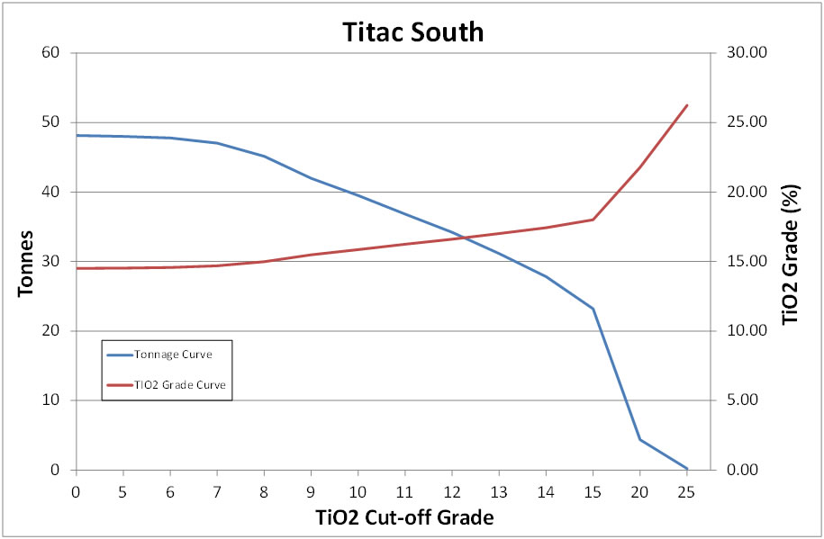
Figure 13.14: Grade Tonnage Curves for the Titac Project
| DJF_MJ/WB | Titac-NI43-101Rpt (4).docx | January 27, 2012 |
| 2CC031.004 – Cardero Resources | |
| Titac Project NI 43-101 | Page 81 |
| 13.14 | Mineral Resource Risks |
|
Ilmenite is an industrial mineral and there are risks and uncertainties associated with this ilmenite resource, many of which are common to industrial mineral deposits. Industrial mineral have special risks that are not typically associated with precious or base metal mines. Special concerns include mineralogy of material, deleterious elements (such as silica, calcium, magnesium and manganese), and special market factors such as market size or proprietary technology. Because of these and other issues, industrial mineral deposits carry additional risk compared to more common metal products. |
| DJF_MJ/WB | Titac-NI43-101Rpt (4).docx | January 27, 2012 |
| 2CC031.004 – Cardero Resources | |
| Titac Project NI 43-101 | Page 82 |
| 14 |
Adjacent Properties |
|
The Project is situated at the western edge of the Duluth geological complex, bordering on the archean Granite-Greenstone Terrains of the Canadian Shield. This area is a prolific mining area, including several massive Taconite (Iron ore) mines of the Mesabi Range. | |
|
The Duluth Complex contains a series of Cu-Ni deposits in close proximity to the Project. These Cu- Ni deposits include Teck’s Mesaba deposits and Polymet’s NorthMet deposit. These deposits lie near the basil contact between the Duluth Complex and the underlying older Precambrian rocks. There are also numerous OUI bodies similar to Titac within 50 km of the Project Area. CIOUS’s other OUI ilmenite project, Longnose which is similar but larger and higher grade than the Project, lies approximately 40 km north of the Project Area. |
| DJF_MJ/WB | Titac-NI43-101Rpt (4).docx | January 27, 2012 |
| 2CC031.004 – Cardero Resources | |
| Titac Project NI 43-101 | Page 83 |
| 15 |
Other Relevant Data and Information |
|
There is no additional data or information not contained in this report which is relevant to the Project. |
| DJF_MJ/WB | Titac-NI43-101Rpt (4).docx | January 27, 2012 |
| 2CC031.004 – Cardero Resources | |
| Titac Project NI 43-101 | Page 84 |
| 16 |
Interpretation and Conclusions |
|
The Titac OUIs are geologically interpreted to be late-stage, intrusions that cut early Duluth Complex intrusives, and are associated with magmatism generated by the 1.1 billion year old Midcontinent Rift system. | |
|
Re-interpretation of a 1967 ground magnetic survey also shows that the Titac intrusion may be a cluster of OUIs. The drilling program conducted in 2010 and 2011 by CIOUS confirmed strong titanium-iron-oxide mineralization at the Project Area, and determined that the Project Area contains at least two intrusions with large zones of titanium-iron-oxide mineralization (Titac North and Titac South). The Titac intrusions are stratigraphically complex with funnel- or pipe-like geometries, and seemingly interlayered peridotite, pyroxenite, massive oxide, and semi-massive oxide. Titac South is at least 490 m thick, and also has a pipe-like geometry. The Titac OUI or OUIs are hosted by a combination of troctolitic rocks of the Western Margin intrusion and anorthositic rocks of the Anorthositic series (Titac). | |
|
Ilmenite and to a lesser extend titaniferous magnetite is used as a source material for titanium used as pigments and as a metal alloy. Rutile is the ideal source material for titanium as it contains nearly twice as much Ti as ilmenite; however ilmenite is by far the more common source. | |
|
Ilmenite is an industrial mineral and there are risks and uncertainties associated with this ilmenite resource, many of which are common to industrial mineral deposits. Industrial mineral have special risks that are not typically associated with precious or base metal mines. Special concerns include mineralogy of material, deleterious elements (such as silica, calcium, magnesium and manganese), and special market factors such as market size or proprietary technology. Because of these and other issues, industrial mineral deposits carry additional risk compared to more common metal products. | |
|
Historic metallurgical tests of the Titac material are very limited. Small scale testing indicates that a viable Ilmenite concentrate could be created from processing of Titac material, although higher than ideal deleterious element values, such as magnesium, may reduce the potential ilmenite product price. The ilmenite may be sold as a concentrate to an existing ilmenite processor as the deposit is amicable to shipping due to its proximity to rail and a short haul to bulk ports on the western shore of Lake Superior. As well, local beneficiation could be considered, particularly when other nearby OUI bodies are considered for increased scale. The main hurdle to overcome with future exploitation of the Titac deposit revolves around metallurgical optimization to create the highest grade concentrate while reducing potential deleterious element contamination of the concentrate. Further economic analysis of this project is anticipated and should include resolution of the mineralogical, metallurgical and processing issues. | |
|
Based upon a relatively simple processing flow sheet for ilmenite concentrate, a recent increase in demand for Ilmenite and the projects close proximity to other bulk mines and inexpensive shipping routes, SRK believes that the Project meets the criteria for having reasonable prospects of economic extraction. | |
|
The mineral resources for Titac South presented in this report represent the first time disclosure of Mineral Resource for the Project . Drilling on the Titac North deposit is insufficient for delineation of the deposit and evaluation of a resource for Titac North has not been undertaken. |
| DJF_MJ/WB | Titac-NI43-101Rpt (4).docx | January 27, 2012 |
| 2CC031.004 – Cardero Resources | |
| Titac Project NI 43-101 | Page 85 |
The Mineral Resource for Titac South at a cut-off grade of 8% TiO2 includes 45.1 million tonnes at an average grade of 15.0% TiO2 . Based on the assumption that all Ti is found within ilmenite, the contained ilmenite in the Mineral Resource includes 12.8 million tonnes at an average grade of 28.5% ilmenite. While not quantified here, the potential for extraction of iron from magnetite exists and would provide an upside to the project. Vanadium may also be of economic interest, but it has not been analyzed by SRK.
| DJF_MJ/WB | Titac-NI43-101Rpt (4).docx | January 27, 2012 |
| 2CC031.004 – Cardero Resources | |
| Titac Project NI 43-101 | Page 86 |
| 17 |
Recommendations |
|
The Project Area is at an early exploration stage and merits additional work. The drilling program conducted in 2010 and 2011 by CIOUS has confirmed strong titanium-iron-oxide mineralization at the Project Area, and determined that the Project Area contains at least two OUIs with large zones of titanium-iron-oxide mineralization (Titac North and Titac South). The Titac South intrusion was extensively drilled by CIOUS in 2010 and 2011, and has been fairly well defined by this drilling. A modest in-fill drilling program is recommended at Titac South to farther define contacts with country rock, and to fill-in local gaps with-in the intrusion. Ore mineral speciation and metallurgical/beneficiation studies, as well as a preliminary economic assessment should also be conducted SRK recommends the following work and expenditures: |
| • |
An in-fill drilling program consisting of six diamond drill holes and ~1,800 m of core is recommended. | |
| • |
A petrographic and mineral chemistry study of typical oxide and sulfide mineralization present at Titac should be conducted to identify the specific oxide and sulfide minerals present, and their elemental make-up. | |
| • |
Metallurgical test work in conjunction with the mineralogical studies, to assist with better understanding of ilmenite an magnetite recovery, project economic analysis: 100 kg composite from sample coarse rejects should be collected that represents average TiO2 grades. | |
| • |
A preliminary economic assessment should be conducted |
A 2011 budget is presented to complete the recommended work program:
Table 17.1: Estimated Cost for the Exploration Program Proposed for the Project.
| Recommendation | Estimated Cost (US$) |
| Titac South in-fill drilling (6 holes/1,800 m @ $180/m*) | 324,000 |
| Petrographic and mineral chemistry study | 20,000 |
| Metallurgical testing | 50,000 |
| Preliminary economic assessment study | 100,000 |
| TOTAL | 494,000 |
*Drilling cost per metre includes: Site and Trail preparation, drilling, sampling, facility/vehicle lease, and staffing
| DJF_MJ/WB | Titac-NI43-101Rpt (4).docx | January 27, 2012 |
| 2CC031.004 – Cardero Resources | |
| Titac Project NI 43-101 | Page 87 |
| 18 | References |
|
Bonnichsen, B., 1972, Southern part of the Duluth Complex in Sims, P.K., and Morey, G.B., eds., Geology of Minnesota: A centennial volume, St. Paul, Minnesota Geological Survey, p. 361-387. | |
|
| |
|
Broderick, T.M., 1917, The relation of the titaniferous magnetites of northeastern Minnesota to the Duluth Gabbro, Economic Geology, v. 12, p. 663-696. | |
|
| |
|
Coleraine Minerals Research Laboratory. April 26, 1996. Preliminary, unpublished report by . B. Niles, Research Coordinator. CMRL/TR-96-29. University of Minnesota – Duluth, Natural Resources Research Institute, 5013 Miller Trunk Highway, Duluth, Minnesota, 55811. | |
|
| |
|
Coleraine Minerals Research Institute,“Pilot Plant Beneficiation Tests of a Bulk Sample of Ilmenite Ore Provided by American Shield Company,” December 1994. CMRL/TR-94-15. University of Minnesota – Duluth, Natural Resources Research Institute, 5013 Miller Trunk Highway, Duluth, Minnesota, 55811. | |
|
| |
|
Hauck, S.A., Severson, M.J., Zanko, L., Barnes, S.J., Morton, P., Alminas, H., Foord, E.E., and Dahlberg, E.H., 1997, An overview of the geology and oxide, sulfide, and platinum-group element mineralization along the western and northern contacts of the Duluth Complex, in Ojakangas, R.W., Dickas, A.B., and Green, J.C., eds., Middle Proterozoic to Cambrian Rifting, Central North America: Boulder, Colorado, Geological Society of America Special Paper 312. | |
|
| |
|
Mainwaring, P.R., and Naldrett, A.J., 1977, Country rock assimilation and genesis of Cu-Ni sulfides in the Water Hen Intrusion, Duluth Complex, Minnesota, Economic Geology, v. 72, 1269-1284. | |
|
| |
|
Miller, J.D., Jr., Green, J.C., Severson, M.J., Chandler, V.W., Hauck, S.A., Peterson, D.M., and Wahl, T.E., 2002, Geology and mineral potential of the Duluth Complex and related rocks of northeastern Minnesota: Minnesota Geological Survey report of Investigations 58, 207 p. | |
|
| |
|
Muhich, T.G., 1993, Movement of titanium across the Duluth Complex-Biwabik Iron Formation contact at Dunka Pit, Mesabi Iron Range, northeastern Minnesota [M.S. thesis], Duluth, University of Minnesota, 154 p. | |
|
| |
|
Niles, H.B., 1971 Assay and Test Results from drill hole number 26002, A Vanadiferous, Titanifeorus Magnetite in the Duluth Gabbro complex, Research Laboratory Technical Repot, 30.015-099(2), 12 p. | |
|
| |
|
Paces, J.B., and Miller, J.D., 1993, Precise U-Pb ages of Duluth Complex and related mafic intrusions, northeastern Minnesota, U.S.A., geochronological insights to physical, petrogenetic, paleomagnetic, and tectono-magmatic processes associated eith the 1.1 Ga Midcontinent Rift System, Journal of Geophysical Research, V. 98, pp. 13997-14013. | |
|
| |
|
Ross, B.A., 1985, A petrologic study of the Bardon Peak peridotite, Duluth Complex [M.S. thesis], Duluth, University of Minnesota, 140 p. | |
|
| |
|
Schiffries, C.M, 1982, The petrogenesis of a platiniferous dunite pipe in the Bushveld Complex: Infiltration metasomatism by a chloride solution, Economic Geology, v. 77, p. 1439-1453. | |
|
| |
|
Severson, M.J., 1988, Geology and structure of a portion of the Partridge River Intrusion: A progress report, Duluth, University of Minnesota, Natural Resources Research Institute, Technical Report, NRRI/GMIN-TR-88-08, 78 p. |
| DJF_MJ/WB | Titac-NI43-101Rpt (4).docx | January 27, 2012 |
| 2CC031.004 – Cardero Resources | |
| Titac Project NI 43-101 | Page 88 |
Severson, M.J., 1991, Geology, mineralization, and geostatistics of the Minnamax/Babbitt Cu-Ni deposit (Local Boy area), Minnesota, Part I: Geology, Duluth, University of Minnesota, Natural Resources Research Institute, Technical Report, NRRI/TR-91/13a, 96 p.
Severson, M.J., 1994, Igneous stratigraphy of the South Kawishiwi Intrusion, Duluth Complex, northeastern Minnesota, Duluth, University of Minnesota, Natural Resources Research Institute, Technical Report, NRRI/TR-93/34, 210 p.
Severson, M.J., 1995, Geology of the southern portion of the Duluth Complex, Duluth, University of Minnesota, Natural Resources Research Institute, Technical Report, NRRI/TR-95/26, 185 p.
Severson, M.J., and Hauck, S.A., 1990, Geology, geochemistry, and stratigraphy of a portion of the Partridge River Intrusion, Duluth, University of Minnesota, Natural Resources Research Institute, Technical Report, NRRI/GMIN-TR-89-11, 230 p.
Viljoen, M.J., and Scoon, R.N., 1985, Distribution and main geologic features of discordant intrusions of iron-rich ultramafic pegmatite in the Bushveld Complex, Economic Geology, v. 80, p. 1109-1128.
Weather.com, December 20, 2010,
http://www.weather.com/outlook/health/fitness/wxclimatology/monthly/USMN0370
Winchell, H.V., 1897, Reputed nickel mines in Minnesota, Engineering Mining Journal, v. 64, p. 578.
| DJF_MJ/WB | Titac-NI43-101Rpt (4).docx | January 27, 2012 |
| 2CC031.004 – Cardero Resources | |
| Titac Project NI 43-101 | Page 89 |
| 19 |
Date and Signature Page |
|
This technical report was written by the following “Qualified Persons”. The effective date of this technical report is January 19th , 2012. |
| Qualified Person | Signature | Date |
| Darrell J. Farrow, Pr.Sci.Nat. | “original signed” | January 27, 2012 |
| Michael D. Johnson, P.Geo | “original signed” | January 27, 2012 |
Reviewed by
| “Original signed” | |
| Dr. Wayne Barnett, Pr.Sci.Nat | |
| Project Reviewer |
All data used as source material plus the text, tables, figures, and attachments of this document have been reviewed and prepared in accordance with generally accepted professional engineering and environmental practices.
| DJF_MJ/WB | Titac-NI43-101Rpt (4).docx | January 27, 2012 |
CERTIFICATE OF QUALIFIED PERSON
To Accompany the report entitled: Technical Report on the Titac Ilmenite Project, Minnesota, USA, January 27, 2012 (“Technical Report”)
I, Michael D. Johnson, residing at 2021 Berkshire Crescent, Coquitlam, BC, V3E 3N5, do hereby certify that:
1) |
I am a Senior Geologist with the firm of SRK Consulting (Canada) Inc. (“SRK”) with an office at Suite 2200, 1066 West Hastings Street, Vancouver, BC, V6E 3X2; |
|
|
2) |
I am a graduate of the Queen’s University, Kingston, Ontario in 1996, where I obtained a B.Sc. (H) in Geological Sciences. I have practiced my profession continuously since graduation in April, 1996. I have been employed as a geologist, exploration manager, mine geologist and open pit mine manager. I have extensive experience in resource estimation within many deposit types. I have worked with ultramafic intrusions and related mineral deposits for more than 10 years; |
|
|
3) |
I am a Professional Geoscientist registered with the Association of Professional Engineers and Geoscientists of BC (registration # 34923); |
|
|
4) |
I have personally inspected the property that is the subject of the Technical Report in March 2010; |
|
|
5) |
I have read the definition of “qualified person” set out in National Instrument 43-101 and certify that by virtue of my education, affiliation to a professional association and past relevant work experience, I fulfill the requirements to be a “qualified person” for the purposes of National Instrument 43-101; |
|
|
6) |
I am responsible for the preparation of Sections 12 and 13 of the Technical Report; |
|
|
7) |
I am independent of the issuer as defined in Section 1.5 of National Instrument 43-101; |
|
|
8) |
I have had no prior involvement with the property that is the subject of the Technical Report. |
|
|
9) |
I have read National Instrument 43-101 and the sections of the Technical Report for which I am responsible have been prepared in compliance therewith; |
|
|
10) |
As of the effective date of the Technical Report, to the best of my knowledge, information and belief, the sections of the Report for which I am responsible contain all scientific and technical information that is required to be disclosed to make the portions of the Technical Report for which I am responsible not misleading; |
| January 27, 2012 | [“signed and sealed”] |
| Vancouver | Michael D. Johnson, P.Geo. |
| Senior Geologist, SRK |
CERTIFICATE OF QUALIFIED PERSON
To accompany the report entitled: Technical Report on the Titac Ilmenite Project, Minnesota, USA, January 27, 2012
I, Darrell Farrow, residing at 40 – 4055 Indian River Drive, North Vancouver, Canada, do hereby certify that:
1) |
I am an associate with the firm of SRK Consulting (Canada) Inc. (“SRK”) with an office at 22nd Floor, 1066 West Hastings Street, Vancouver, BC, Canada; |
|
2) |
I am a graduate of the University of Pretoria, Pretoria, South Africa (M.Sc. Geology 1989) and the University of Cape Town, Cape Town, South Africa (B.Sc.(Hons) 1982). I have practiced my profession continuously since graduation and have been employed as a research geochemist for four years, as a geologist at two mining operations over a period of ten years, as a manager of an exploration laboratory for three years, and as a consulting geologist for eleven years; |
|
3) |
I am a Professional Natural Scientist in the field of practice of Geological Science, registered as a member of the South African Council for Natural Scientific Professions, South Africa, Reg. No. 400163/07; |
|
4) |
I have not personally inspected the property that is the subject of the Technical Report but have relied on a site visit conducted by Mike Johnson P.Geo., co-author of this technical report in March 2010; |
|
5) |
I have read the definition of “qualified person” set out in National Instrument 43-101 and certify that by virtue of my education, affiliation to a professional association and past relevant work experience, I fulfill the requirements to be a “qualified person” for the purposes of National Instrument 43-101 and the sections to which I have contributed in this technical report have been prepared in compliance with National Instrument 43-101 and Form 43-101F1; |
|
6) |
I as a qualified person am independent of the issuer as defined in Section 1.5 of National Instrument 43- 101; |
|
7) |
I am a co-author of this report and responsible for all sections except sections 12 and 13; |
|
8) |
I have had no prior involvement with the property that is the subject of the Technical Report; |
|
9) |
I have read National Instrument 43-101 and confirm that the sections of the Technical Report for which I am responsible have been prepared in compliance therewith; |
|
10) |
As of the effective date of the Technical Report, to the best of my knowledge, information and belief, the sections of the Technical Report for which I am responsible contain all scientific and technical information that is required to be disclosed to make the portions of the Technical Report for which I am responsible not misleading. |
| [“signed and sealed”] | |
| Vancouver | Darrell Farrow, M.Sc., Pr.Sci.Nat. |
| January, 27, 2012 |