NI 43-101
Compliant
TECHNICAL
REPORT
on
the
LOOKOUT
HILL PROJECT
Ömnögovi
Aimag, Southern Mongolia
Prepared
for:
Entrée
Gold Inc.
1201
- 1166 Alberni Street
Vancouver,
BC
Canada
|
June
10, 2009
|
Prepared
by: John
Vann, F.AusIMM, M.AIG
Scott
Jackson, M.AusIMM
Owen
Cullingham, P.Geol.
Dean
David, M.AusIMM
Robert
M Cann, P. Geo.
James
R. Foster, P.Geo.
|
CERTIFICATES AND
CONSENT LETTER
 Quantitative Group
Our
Skills On Your
Team TM
|
Geostatistics
Resources
& Reserves
Reconciliation
& Grade Control
Audit
& Due Diligence
Strategic
Mine Planning
Geometallurgical
Modelling
Mine
Geology
Training
|
John
Vann
Suite 10/18 Parry
St, Fremantle,
WA, 6160,
Australia
Tel.:
+61 8 9433 3511
Fax:
+61 8 9433 3611
Email:
jv@qgroup.net.au
CONSENT
|
To:
|
Toronto
Stock Exchange
|
British
Columbia Securities Commission
Alberta
Securities Commission
Saskatchewan
Securities Commission
Manitoba
Securities Commission
Ontario
Securities Commission
New
Brunswick Securities Commission
Nova
Scotia Securities Commission
Prince
Edward Island Securities Commission
Newfoundland
and Labrador Securities Commission
|
And
To:
|
Entrée
Gold Inc.
|
I, John Vann, do
hereby consent to the public filing of the technical report prepared for Entrée
Gold Inc. titled ‘NI 43-101 Compliant Technical Report on the Lookout Hill
Project, Omnogovi Aimag, Southern Mongolia’, with an effective date of June 10,
2009 (the “Technical Report”) with the securities regulatory authorities
referred to above.
I further consent
(a) to the public filing of the Technical Report with any stock exchange and
other regulatory authority and any publication of the Technical Report by them
for regulatory purposes, including electronic publication in the public company
files on their websites accessible by the public, and (b) to the publication of
the Technical Report by Entrée Gold Inc. on its company website or
otherwise.
Dated this 26th day
of June, 2009.
“Signed
and sealed”
__________________________
John Vann,
M.AusIMM
Quantitative Geoscience Pty Ltd (ABN 30 095 494 947)
and Quantitative Group Pty Ltd (ABN 61 120 267 192). trading as QG
address: Suite 12, 18 Parry St Fremantle WA.
Australia 6160 (PO Box 1304 Fremantle WA. Australia 6959)
phone: +61 (0) 8 9433 3511 | fax: +61 (0) 8 9433 3611 | email: info@qgroup.net.au | web:
www.qgroup.net.au
|
Quantitative Group
Our
Skills On Your
Team TM
|
Geostatistics
Resources
& Reserves
Reconciliation
& Grade Control
Audit
& Due Diligence
Strategic
Mine Planning
Geometallurgical
Modelling
Mine
Geology
Training
|
CERTIFICATE
of AUTHOR
John
Vann
Suite 10/18 Parry
St, Fremantle,
WA, 6160,
Australia
Tel.:
+61 8 9433 3511
Fax:
+61 8 9433 3611
Email:
jv@qgroup.net.au
I,
John Edward Vann, do hereby certify that:
|
1.
|
I am
currently employed as Principal Consultant and Director
by:
|
Quantitative Group
Pty Ltd.
Suite 10/18 Parry
St, Fremantle,
WA, 6160,
Australia
|
2.
|
I graduated
from the Royal Melbourne Institute of Technology, Victoria, Australia with
a Bachelor of Applied Science (with Distinction) in Applied Geology in
1984. I also graduated from the University of New England, NSW, Australia
with a Bachelor of Science (with Honours) in Geology in 1985. I further
graduated from the University of Leeds, United Kingdom, with the degree
Master of Science in Mining Geostatistics (with Distinction) in
1993.
|
|
3.
|
I am a Fellow
of the Australasian Institute of Mining and Metallurgy (no. 103352) and
also a Member of the Australian Institute of Geoscientists and a Member of
the Society for Economic Geology.
|
|
4.
|
I have
practised my profession continuously since 1985 and have experience in
mining operations, consulting and professional development teaching at and
for mines in various countries including Australia, Canada, The United
States of America, The United Kingdom, Indonesia, Laos, Mongolia, New
Caledonia, New Zealand, Papua New Guinea, Zimbabwe and South Africa. I
have specific experience in large porphyry Cu-Au deposits such as Ok Tedi
and Cadia Hill. As a result of my qualifications and experience, I am a
Qualified Person as defined in National Instrument
43-101.
|
|
5.
|
I have read
the definition of “qualified person” set out in National Instrument 43-
101 (“NI 43-101”) and certify that by reason of my education, affiliation
with a professional association (as defined in NI 43-101) and past
relevant work experience, I fulfil the requirements to be a “qualified
person” for the purposes of NI
43-101.
|
|
6.
|
I am
responsible for the preparation of sections pertaining to the Javhlant
MEL, the Heruga deposit (Sections 1.4, 7.2.3, 9.2, 11.3, 12.2.2, 14.2,
17.2, 20.1.3, and 21.1.3) and the Hugo North Extension Resource (Sections
1.3, 7.2.1, 9.1, 11.2.2, 11.2.3, 12.2.1, 13.3.3, 14.1, 17.1, 20.1.1, and
21.1.1) of the technical report titled “NI 43-101 Compliant Technical
Report on the Lookout Hill Project, Omnogovi Aimag, Southern Mongolia,”
with an effective date of 10 June 2009 (the “Technical Report”) relating
to the Lookout Hill Property. I am the QP with overall responsibility for
report preparation and preparation of any report sections not specifically
assigned to other QPs in Section 2 of the Technical Report. I visited the
Lookout Hill Project February 19-26, 2008 and September 2-9, 2008. I have
personally visited Heruga, and Hugo North Extension, Southern Oyu, Zone I
and Zone III mentioned in this
report.
|
Quantitative Geoscience Pty Ltd (ABN 30 095 494 947)
and Quantitative Group Pty Ltd (ABN 61 120 267 192). trading as QG
address: Suite 12, 18 Parry St Fremantle WA.
Australia 6160 (PO Box 1304 Fremantle WA. Australia 6959)
phone: +61 (0) 8 9433 3511 | fax: +61 (0) 8 9433 3611 | email: info@qgroup.net.au | web:
www.qgroup.net.au
|
Quantitative Group
Our
Skills On Your
Team TM
|
Geostatistics
Resources
& Reserves
Reconciliation
& Grade Control
Audit
& Due Diligence
Strategic
Mine Planning
Geometallurgical
Modelling
Mine
Geology
Training
|
|
7.
|
I have not
had prior involvement with the properties that are the subject of the
Technical Report.
|
|
8.
|
As of the
date of the certificate, to the best of my knowledge, information and
belief, the Technical Report contains all scientific and technical
information that is required to be disclosed to make the Technical Report
not misleading.
|
|
9.
|
I am
independent of the issuer applying all of the tests in Section 1.4 of
National Instrument 43-101. I do not own any shares of Entrée
Gold Inc.
|
|
10.
|
I have read
National Instrument 43-101 and Form 43-101F1, and the Technical Report has
been prepared in compliance with that instrument and
form.
|
|
11.
|
I consent to
the filing of the Technical Report with any stock exchange and other
regulatory authority and any publication by them, including electronic
publication in the public company files on their websites accessible by
the public.
|
Dated this 10th day
of June, 2009.
“Signed
and sealed”
__________________________
John Edward Vann,
F.AusIMM, M.AIG
Quantitative Geoscience Pty Ltd (ABN 30 095 494 947)
and Quantitative Group Pty Ltd (ABN 61 120 267 192). trading as QG
address: Suite 12, 18 Parry St Fremantle WA.
Australia 6160 (PO Box 1304 Fremantle WA. Australia 6959)
phone: +61 (0) 8 9433 3511 | fax: +61 (0) 8 9433 3611 | email: info@qgroup.net.au | web:
www.qgroup.net.au
|
Quantitative Group
Our
Skills On Your
Team TM
|
Geostatistics
Resources
& Reserves
Reconciliation
& Grade Control
Audit
& Due Diligence
Strategic
Mine Planning
Geometallurgical
Modelling
Mine
Geology
Training
|
Scott Jackson,
M.AusIMM
Suite 10/18 Parry
St, Fremantle,
WA, 6160,
Australia
Tel.:
+61 8 9433 3511
Fax:
+61 8 9433 3611
Email:
sj@qgroup.net.au
CONSENT
|
To:
|
Toronto
Stock Exchange
|
British
Columbia Securities Commission
Alberta
Securities Commission
Saskatchewan
Securities Commission
Manitoba
Securities Commission
Ontario
Securities Commission
New
Brunswick Securities Commission
Nova
Scotia Securities Commission
Prince
Edward Island Securities Commission
Newfoundland
and Labrador Securities Commission
|
And
To:
|
Entrée
Gold Inc.
|
I, Scott Jackson,
do hereby consent to the public filing of the technical report prepared for
Entrée Gold Inc. titled ‘NI 43-101 Compliant Technical Report on the Lookout
Hill Project, Omnogovi Aimag, Southern Mongolia’, with an effective date of June
10, 2009 (the “Technical Report”) with the securities regulatory authorities
referred to above.
I further consent
(a) to the public filing of the Technical Report with any stock exchange and
other regulatory authority and any publication of the Technical Report by them
for regulatory purposes, including electronic publication in the public company
files on their websites accessible by the public, and (b) to the publication of
the Technical Report by Entrée Gold Inc. on its company website or
otherwise.
Dated this 26th day
of June, 2009.
“Signed
and sealed”
__________________________
Scott Jackson,
M.AusIMM
Quantitative Geoscience Pty Ltd (ABN 30 095 494 947)
and Quantitative Group Pty Ltd (ABN 61 120 267 192). trading as QG
address: Suite 12, 18 Parry St Fremantle WA.
Australia 6160 (PO Box 1304 Fremantle WA. Australia 6959)
phone: +61 (0) 8 9433 3511 | fax: +61 (0) 8 9433 3611 | email: info@qgroup.net.au | web:
www.qgroup.net.au
|
Quantitative Group
Our
Skills On Your
Team TM
|
Geostatistics
Resources
& Reserves
Reconciliation
& Grade Control
Audit
& Due Diligence
Strategic
Mine Planning
Geometallurgical
Modelling
Mine
Geology
Training
|
CERTIFICATE
of AUTHOR
Scott
Jackson
Suite 10/18 Parry
St, Fremantle,
WA, 6160,
Australia
Tel.:
+61 8 9433 3511
Fax:
+61 8 9433 3611
Email:
sj@qgroup.net.au
I,
Scott Jackson, do hereby certify that:
|
1.
|
I am
currently employed as Principal Consultant and Director
by:
|
Quantitative Group
Pty Ltd.
Suite 10/18 Parry
St, Fremantle,
WA, 6160,
Australia
|
2.
|
I graduated
with a B.Sc. degree in Honours Geology from The University of Western
Australia in 1990. In addition, I obtained a CFSG (Mining Geostatistics
degree) from the Paris School of Mines in
1998.
|
|
3.
|
I am a
registered member of the Australasian Institute of Mining and Metallurgy.
I am also a member of the Australian Institute of
Geoscientists.
|
|
4.
|
I have worked
as a geologist for more than 18 years since my graduation from university.
I have worked on porphyry and epithermal systems in Australia, Indonesia,
New Zealand and Papua New Guinea.
|
|
5.
|
I have read
the definition of “qualified person” set out in National Instrument 43-
101 (“NI 43-101”) and certify that by reason of my education, affiliation
with a professional association (as defined in NI 43-101) and past
relevant work experience, I fulfil the requirements to be a “qualified
person” for the purposes of NI
43-101.
|
|
6.
|
I am
responsible for the preparation of sections pertaining to the Javhlant
MEL, the Heruga deposit (Sections 1.4, 7.2.3, 9.2, 11.3, 12.2.2, 14.2,
17.2, 20.1.3, and 21.1.3) and the Hugo North Extension Resource (Sections
1.3, 7.2.1, 9.1, 11.2.2, 11.2.3, 12.2.1, 13.3.3, 14.1, 17.1, 20.1.1, and
21.1.1) of the technical report titled “NI 43-101 Compliant Technical
Report on the Lookout Hill Project, Omnogovi Aimag, Southern Mongolia,”
with an effective date of 10 June 2009 (the “Technical Report”)
relating to the Lookout Hill Property. I am the QP with overall
responsibility for report preparation and preparation of any report
sections not specifically assigned to other QPs in Section 2 of the
Technical Report. I visited the Lookout Hill Project February 19-22, 2008
and September 2-9, 2008. . I have personally visited Heruga, and Hugo
North Extension, Southern Oyu, Zone I and Zone III mentioned in this
report.
|
|
7.
|
I have not
had prior involvement with the properties that are the subject of the
Technical Report.
|
Quantitative Geoscience Pty Ltd (ABN 30 095 494 947)
and Quantitative Group Pty Ltd (ABN 61 120 267 192). trading as QG
address: Suite 12, 18 Parry St Fremantle WA.
Australia 6160 (PO Box 1304 Fremantle WA. Australia 6959)
phone: +61 (0) 8 9433 3511 | fax: +61 (0) 8 9433 3611 | email: info@qgroup.net.au | web:
www.qgroup.net.au
|
Quantitative Group
Our
Skills On Your
Team TM
|
Geostatistics
Resources
& Reserves
Reconciliation
& Grade Control
Audit
& Due Diligence
Strategic
Mine Planning
Geometallurgical
Modelling
Mine
Geology
Training
|
|
8.
|
As of the
date of the certificate, to the best of my knowledge, information and
belief, the Technical Report contains all scientific and technical
information that is required to be disclosed to make the Technical Report
not misleading.
|
|
9.
|
I am
independent of the issuer applying all of the tests in Section 1.4 of
National Instrument 43-101. I do not own any shares of Entrée
Gold Inc.
|
|
10.
|
I have read
National Instrument 43-101 and Form 43-101F1, and the Technical Report has
been prepared in compliance with that instrument and
form.
|
|
11.
|
I consent to
the filing of the Technical Report with any stock exchange and other
regulatory authority and any publication by them, including electronic
publication in the public company files on their websites accessible by
the public.
|
Dated this 10th day
of June, 2009.
“Signed
and sealed”
__________________________
Scott Jackson,
M.AusIMM
Quantitative Geoscience Pty Ltd (ABN 30 095 494 947)
and Quantitative Group Pty Ltd (ABN 61 120 267 192). trading as QG
address: Suite 12, 18 Parry St Fremantle WA.
Australia 6160 (PO Box 1304 Fremantle WA. Australia 6959)
phone: +61 (0) 8 9433 3511 | fax: +61 (0) 8 9433 3611 | email: info@qgroup.net.au | web:
www.qgroup.net.au
Owen
R. Cullingham, P. Geol., P.Geo.
128
Oakcliffe Place S.W.
Calgary,
Alberta T2V 0J8
Tel.:
(403) 281-5755
Fax:
(403) 281-5761
Email:
ocullingham@shaw.ca
CONSENT
|
To:
|
Toronto
Stock Exchange
|
British Columbia Securities
Commission
Alberta Securities
Commission
Saskatchewan Securities
Commission
Manitoba Securities
Commission
Ontario Securities
Commission
New Brunswick Securities
Commission
Nova Scotia Securities
Commission
Prince Edward Island Securities
Commission
Newfoundland and Labrador Securities
Commission
|
And
To:
|
Entrée
Gold Inc.
|
I, Owen R.
Cullingham, do hereby consent to the public filing of the technical report
prepared for Entrée Gold Inc. titled ‘NI 43-101 Compliant Technical Report on
the Lookout Hill Project, Omnogovi Aimag, Southern Mongolia’, with an effective
date of June 10, 2009 (the “Technical Report”) with the securities regulatory
authorities referred to above.
I further consent
(a) to the public filing of the Technical Report with any stock exchange and
other regulatory authority and any publication of the Technical Report by them
for regulatory purposes, including electronic publication in the public company
files on their websites accessible by the public, and (b) to the publication of
the Technical Report by Entrée Gold Inc. on its company website or
otherwise.
Dated this 26th day
of June, 2009.
“signed
and sealed”
__________________________
Owen R. Cullingham,
P.Geol., P.Geo.
CERTIFICATE
of AUTHOR
Owen R. Cullingham,
P. Geol., P. Geo.
128 Oakcliffe Place
S.W.
Calgary,
Alberta T2V 0J8
Tel.:
(403) 281-5755
Fax:
(403) 281-5761
Email:
ocullingham@shaw.ca
I, Owen R.
Cullingham, P. Geol., P. Geo., do hereby certify that:
|
1.
|
I am an
independent coal consultant based in Calgary, Alberta, Canada and was
contracted by:
|
Entrée Gold
Inc.
1201-1166 Alberni
Street
Vancouver,
BC
V6E
3Z3
|
2.
|
I graduated
with a B.Sc. degree in Geology from the University of Calgary in
1971.
|
|
3.
|
I am a
registered member of the Association of Professional Engineers and
Geoscientists of British Columbia, licence number # 20409. I am also a
member of the Association of Professional Engineers, Geologists and
Geophysicists of Alberta, member #
M33886.
|
|
4.
|
I have worked
as a geologist for more than 35 years since my graduation from
university.
|
|
5.
|
I have read
the definition of “qualified person” set out in National Instrument 43-
101 (“NI 43-101”) and certify that by reason of my education, affiliation
with a professional association (as defined in NI 43-101) and past
relevant work experience, I fulfill the requirements to be a “qualified
person” for the purposes of NI
43-101.
|
|
6.
|
I am the QP
responsible (together with James R. Foster) for the preparation of
Sections 8.4, 9.3.3, 10.2.5, 12.3.2, 13.4.5, 20.2.2, 21.2 related to coal
exploration on the Western MEL’s (100% Entrée) of the NI 43-101 Compliant
technical report titled “Technical Report on the Lookout Hill Project,
Omnogovi Aimag, Southern Mongolia,” with an effective date of June 10,
2009 (the “Technical Report”) relating to the Lookout Hill Property. I
visited the Nomkhon Bohr coal project from October 4-14,
2008.
|
|
7.
|
I have not
had prior involvement with the properties that are the subject of the
Technical Report.
|
|
8.
|
As of the
date of the certificate, to the best of my knowledge, information and
belief, I am not aware of any material fact or material change with
respect to the subject matter of the technical report, the omission to
disclose which makes the technical report
misleading.
|
|
10.
|
I am
independent of the issuer applying all of the tests in Section 1.5 of
National Instrument 43-101 and do not own any shares of Entrée Gold
Inc.
|
|
11.
|
I have read
National Instrument 43-101 and Form 43-101F1, and the Technical Report has
been prepared in compliance with that instrument and
form.
|
|
12.
|
I consent to
the filing of the Technical Report with any stock exchange and other
regulatory authority and any publication by them, including electronic
publication in the public company files on their websites accessible by
the public.
|
Dated this 10th day
of June, 2009.
“Signed
and sealed”
__________________________
Owen Cullingham,
B.Sc., P.Geol., P.Geo.
|
Level
14 / 140 St Georges Terrace
Perth
Western Australia 6000
GPO Box
Z5266
Perth
Western Australia 6831
|
Telephone:
61 8 9347 4777
Facsimile:
61 8 9347 4747
www.minproc.com.au
ABN
52
DOB 992 694
|
 |
Dean David,
M.AusIMM
14/140 St Georges
Tce,
Perth, WA
6000 Australia
Tel.:
+61 8 9347 4734
Fax:
+61 8 9347 4747
Email:
dean.david@minproc.com.au
CONSENT
|
To:
|
Toronto
Stock Exchange
|
British
Columbia Securities Commission
Alberta
Securities Commission
Saskatchewan
Securities Commission
Manitoba
Securities Commission
Ontario
Securities Commission
New
Brunswick Securities Commission
Nova
Scotia Securities Commission
Prince
Edward Island Securities Commission
Newfoundland
and Labrador Securities Commission
|
And
To:
|
Entrée
Gold Inc.
|
I, Dean David, do
hereby consent to the public filing of the technical report prepared for Entrée
Gold Inc. titled ‘NI 43-101 Compliant Technical Report on the Lookout Hill
Project, Omnogovi Aimag, Southern Mongolia’, with an effective date of June 10,
2009 (the “Technical Report”) with the securities regulatory authorities
referred to above.
I further consent
(a) to the public filing of the Technical Report with any stock exchange and
other regulatory authority and any publication of the Technical Report by them
for regulatory purposes, including electronic publication in the public company
files on their websites accessible by the public, and (b) to the publication of
the Technical Report by Entrée Gold Inc. on its company website or
otherwise.
Dated this 26th day
of June, 2009.
“Signed
and sealed”
__________________________
Dean David,
M.AusIMM
|
Level
14 / 140 St Georges Terrace
Perth
Western Australia 6000
GPO Box
Z5266
Perth
Western Australia 6831
|
Telephone:
61 8 9347 4777
Facsimile:
61 8 9347 4747
www.minproc.com.au
ABN
52
DOB 992 694
|
|
CERTIFICATE
of AUTHOR
Dean
David
14/140 St Georges
Tce,
Perth, WA
6000 Australia
Tel.:
+61 8 9347 4734
Fax:
+FAX
Email:
dean.david@minproc.com.au
I,
Dean David, do hereby certify that:
|
1.
|
I am
currently employed as Process Consultant
by:
|
|
|
GRD
Minproc
|
|
|
14/140 St
Georges Tce,
|
|
|
Perth, WA
6000 Australia
|
|
2.
|
I graduated
from the South Australian Institute of Technology (Now University of South
Australia) in 1982 with a Bachelor of Applied Science in
Metallurgy.
|
|
3.
|
I am a member
of the Australasian Institute of Mining and Metallurgy
(no.102351).
|
|
4.
|
I have
practised my profession as a metallurgist for a total of 23 years and with
GRD Minproc since October 2003. As a result of my experience and
qualifications, I am a Qualified Person as defined in National Instrument
43-101.
|
|
5.
|
I have read
the definition of “qualified person” set out in National Instrument 43-
101 (“NI 43-101”) and certify that by reason of my education, affiliation
with a professional association (as defined in NI 43-101) and past
relevant work experience, I fulfil the requirements to be a “qualified
person” for the purposes of NI
43-101.
|
|
6.
|
I am
responsible for the preparation of Section 16 and 21.1.1 of the technical
report titled “NI 43-101 Compliant Technical Report on the Lookout Hill
Project, Omnogovi Aimag, Southern Mongolia,” with an effective date of
June 10th,
2009 (the “Technical Report”) relating to the Lookout Hill
Property. I have not visited the property and have relied on
the visit in December 2005 by a Principal Process Engineer and visits to
site and Mongolia for the Lookout Hill Project by others employed by GRD
Minproc Limited in 2007.
|
|
7.
|
I have not
had prior involvement with the properties that are the subject of the
Technical Report.
|
|
8.
|
As of the
date of the certificate, to the best of my knowledge, information and
belief, the Technical Report contains all scientific and technical
information that is required to be disclosed to make the Technical Report
not misleading..
|
|
Level
14 / 140 St Georges Terrace
Perth
Western Australia 6000
GPO Box
Z5266
Perth
Western Australia 6831
|
Telephone:
61 8 9347 4777
Facsimile:
61 8 9347 4747
www.minproc.com.au
ABN
52
DOB 992 694
|
|
|
9.
|
I am
independent of the issuer applying all of the tests in Section 1.4 of
National Instrument 43-101. I do not own any shares of Entrée
Gold Inc.
|
|
10.
|
I have read
National Instrument 43-101 and Form 43-101F1, and the Technical Report has
been prepared in compliance with that instrument and
form.
|
|
11.
|
I consent to
the filing of the Technical Report with any stock exchange and other
regulatory authority and any publication by them, including electronic
publication in the public company files on their websites accessible by
the public.
|
Dated this 10th day
of June, 2009.
“Signed
and sealed”
__________________________
Dean David, M.
AusIMM

|
Robert
M. Cann, P.Geo.
|
||
|
1201-1166
Alberni Street
|
||
|
Vancouver,
BC V6E 3Z3
|
Tel.:
(604) 687-4777
Fax:
(604) 687-4770
Email:
rcann@entreegold.com
CONSENT
|
To:
|
Toronto
Stock Exchange
|
British
Columbia Securities Commission
Alberta
Securities Commission
Saskatchewan
Securities Commission
Manitoba
Securities Commission
Ontario
Securities Commission
New
Brunswick Securities Commission
Nova
Scotia Securities Commission
Prince
Edward Island Securities Commission
Newfoundland
and Labrador Securities Commission
|
And
To:
|
Entrée
Gold Inc.
|
I, Robert Cann, do
hereby consent to the public filing of the technical report prepared for Entrée
Gold Inc. titled ‘NI 43-101
Compliant Technical Report on the Lookout Hill Project, Omnogovi Aimag, Southern
Mongolia’, with an effective date of June 10, 2009 (the “Technical
Report”) with the securities regulatory authorities referred to
above.
I further consent
(a) to the public filing of the Technical Report with any stock exchange and
other regulatory authority and any publication of the Technical Report by them
for regulatory purposes, including electronic publication in the public company
files on their websites accessible by the public, and (b) to the publication of
the Technical Report by Entrée Gold Inc. on its company website or
otherwise.
Dated this 26th day
of June 2009.
“Signed
and sealed”
__________________________
Robert M. Cann,
M.Sc., P.Geo
CERTIFICATE
of AUTHOR
Robert M. Cann,
P.Geo.
1201-1166 Alberni
Street
Vancouver,
BC V6E 3Z3
Tel.:
(604) 687-4777
Fax:
(604) 687-4770
Email:
rcann@entreegold.com
I,
Robert M. Cann, P.Geo., do hereby certify that:
|
|
1.
|
I am
currently employed as Vice-President, Exploration
by:
|
Entrée Gold
Inc.
1201-1166 Alberni
Street
Vancouver,
BC
V6E
3Z3
|
|
2.
|
I graduated
with a B.Sc. degree in Honours Geology from The University of British
Columbia in 1976. In addition, I obtained a M.Sc. degree in Economic
Geology from The University of British Columbia in
1979.
|
|
|
3.
|
I am a
registered member of the Association of Professional Engineers and
Geoscientists of British Columbia. I am also a member of the Canadian
Institute of Mining and Metallurgy (CIMM) and the Society of Economic
Geologists (SEG).
|
|
|
4.
|
I have worked
as a geologist for more than 25 years since my graduation from university.
I have worked on porphyry and epithermal systems in Canada, USA, Mexico,
Central America, and South America.
|
|
|
5.
|
I have read
the definition of “qualified person” set out in National Instrument 43-
101 (“NI 43-101”) and certify that by reason of my education, affiliation
with a professional association (as defined in NI 43-101) and past
relevant work experience, I fulfill the requirements to be a “qualified
person” for the purposes of NI
43-101.
|
|
|
6.
|
I assisted,
under the direct supervision of Quantitative Group, in preparation of
Sections 1.5, 4.2.2, 6.3, 7.3, 9.3, 10.2, 11.4, 12.3, 13.4, 14.3, 20.2 and
21.2 related to the Western MEL’s (100% Entrée) of the NI 43-101 Compliant
technical report titled “Technical Report on the Lookout Hill Project,
Omnogovi Aimag, Southern Mongolia,” with an effective date of June 10,
2009 (the “Technical Report”) relating to the Lookout Hill
Property.
|
|
Entrée
Gold Inc.
|
Entrée
LLC
|
www.entreegold.com
|
|
Suite 1201
|
Jamyan Gun
Street-5
|
TSX:
ETG
|
||
|
1166 Alberni
St.
|
Ar Mongol
Travel Building
|
AMEX:
EGI
|
||
|
Vancouver, BC
V6E 3Z3
|
Suite #201,
#202
|
Frankfurt:
EKA
|
||
|
Tel:
604.687.4777 Fax: 604.687.4770
|
Sukhbaatar
District, 1st County
|
|||
|
Ulaanbaatar,
Mongolia
|
||||
|
Tel:
976.11.330953 Fax: 976.11.319426
|
|
|
7.
|
I am the Vice
President, Exploration responsible for overall project management on the
100% Entrée ground (Western MEL’s). I have made four site
visits (in February, June, August and November) to the Oyu Tolgoi project
and Lookout Hill project in 2008.
|
|
|
8.
|
I have not
had prior involvement with the properties that are the subject of the
Technical Report.
|
|
|
9.
|
As of the
date of the certificate, to the best of my knowledge, information and
belief, I am not aware of any material fact or material change with
respect to the subject matter of the technical report, the omission to
disclose which makes the technical report
misleading.
|
|
|
10.
|
I am not
independent of the issuer applying all of the tests in Section 1.5 of
National Instrument 43-101 because I have been a full-time employee of
Entrée Gold Inc. since July 2002. I currently own 31,000 shares
of Entrée Gold Inc.; and, I hold stock options granted by Entrée Gold Inc.
to acquire up to 725,000 shares.
|
|
|
11.
|
I have read
National Instrument 43-101 and Form 43-101F1, and the Technical Report has
been prepared in compliance with that instrument and
form.
|
|
|
12.
|
I consent to
the filing of the Technical Report with any stock exchange and other
regulatory authority and any publication by them, including electronic
publication in the public company files on their websites accessible by
the public.
|
Dated this 10th day
of June, 2009.
“Signed
and sealed”
__________________________
Robert M. Cann,
M.Sc., P.Geo.
|
James
R. Foster, H.B.Sc., P.Geo.
|
||
|
1201-1166
Alberni Street
|
||
|
Vancouver,
BC V6E 3Z3
|
Tel.:
(604) 687-4777
Fax:
(604) 687-4770
Email:
jfoster@entreegold.com
CONSENT
|
To:
|
Toronto
Stock Exchange
|
British
Columbia Securities Commission
Alberta
Securities Commission
Saskatchewan
Securities Commission
Manitoba
Securities Commission
Ontario
Securities Commission
New
Brunswick Securities Commission
Nova
Scotia Securities Commission
Prince
Edward Island Securities Commission
Newfoundland
and Labrador Securities Commission
|
And
To:
|
Entrée
Gold Inc.
|
I, James R. Foster,
do hereby consent to the public filing of the technical report prepared for
Entrée Gold Inc. titled ‘NI 43-101 Compliant Technical Report on the Lookout
Hill Project, Omnogovi Aimag, Southern Mongolia’, with an effective date of June
10, 2009 (the “Technical Report”) with the securities regulatory authorities
referred to above.
I further consent
(a) to the public filing of the Technical Report with any stock exchange and
other regulatory authority and any publication of the Technical Report by them
for regulatory purposes, including electronic publication in the public company
files on their websites accessible by the public, and (b) to the publication of
the Technical Report by Entrée Gold Inc. on its company website or
otherwise.
Dated this 26th day
of June, 2009.
“Signed
and sealed”
__________________________
James R. Foster,
H.B.Sc., P.Geo
CERTIFICATE
of AUTHOR
James R. Foster,
H.B.Sc., P.Geo.
1201-1166 Alberni
Street
Vancouver,
BC V6E 3Z3
Tel.:
(604) 687-4777
Fax:
(604) 687-4770
Email:
jfoster@entreegold.com
I,
James R. Foster, H.B.Sc., P.Geo., do hereby certify that:
|
1.
|
I am
currently employed as Project Manager
by:
|
Entrée Gold
Inc.
1201-1166 Alberni
Street
Vancouver,
BC
V6E
3Z3
|
2.
|
I graduated
with an Honours B.Sc. degree in Earth Science and Geography from The
University of Waterloo in 1979.
|
|
3.
|
I am a
registered member of the Association of Professional Engineers and
Geoscientists of British Columbia. I am also a member of the Society of
Economic Geologists (SEG).
|
|
4.
|
I have worked
as a geologist for more than 25 years since my graduation from university.
I have worked on porphyry and epithermal systems in Canada, USA, Mexico,
Central America, and South America.
|
|
5.
|
I have read
the definition of “qualified person” set out in National Instrument 43-
101 (“NI 43-101”) and certify that by reason of my education, affiliation
with a professional association (as defined in NI 43-101) and past
relevant work experience, I fulfill the requirements to be a “qualified
person” for the purposes of NI
43-101.
|
|
6.
|
I assisted in
preparation of Sections 1.5, 4.2.2, 6.3, 7.3, 9.3, 10.2, 11.4, 12.3, 13.4,
14.3, 20.2 and 21.2 related to the Western MELs (100% Entrée) of the NI
43-101 Compliant technical report titled “Technical Report on the Lookout
Hill Project, Omnogovi Aimag, Southern Mongolia,” with an effective date
of 10 June 2009 (the “Technical Report”) relating to the Lookout Hill
Property. I was the Project Manager responsible for day to day project
management on the 100% Entrée ground and was almost continuously on site
from April 2008 to December 2008. During this period, I also
made numerous site visits to Ivanhoe Mines project site to review
exploration progress and results from the Heruga drilling
project.
|
|
Entrée
Gold Inc.
|
Entrée
LLC
|
www.entreegold.com
|
|
Suite 1201
|
Jamyan Gun
Street-5
|
TSX:
ETG
|
||
|
1166 Alberni
St.
|
Ar Mongol
Travel Building
|
AMEX:
EGI
|
||
|
Vancouver, BC
V6E 3Z3
|
Suite #201,
#202
|
Frankfurt:
EKA
|
||
|
Tel:
604.687.4777 Fax: 604.687.4770
|
Sukhbaatar
District, 1st County
|
|||
|
Ulaanbaatar,
Mongolia
|
||||
|
Tel:
976.11.330953 Fax: 976.11.319426
|
|
7.
|
I have not
had prior involvement with the properties that are the subject of the
Technical Report.
|
|
8.
|
As of the
date of the certificate, to the best of my knowledge, information and
belief, I am not aware of any material fact or material change with
respect to the subject matter of the technical report, the omission to
disclose which makes the technical report
misleading.
|
|
9.
|
I am not
independent of the issuer applying all of the tests in Section 1.5 of
National Instrument 43-101 because I have been under contract or have been
an employee of Entrée Gold Inc. since July 2006. I currently
own Nil shares of Entrée Gold Inc.; and I do hold stock options granted by
Entrée Gold Inc. to acquire up to 240,000
shares.
|
|
10.
|
I have read
National Instrument 43-101 and Form 43-101F1, and the Technical Report has
been prepared in compliance with that instrument and
form.
|
|
11.
|
I consent to
the filing of the Technical Report with any stock exchange and other
regulatory authority and any publication by them, including electronic
publication in the public company files on their websites accessible by
the public.
|
Dated this 10th day
of June, 2009.
“Signed
and sealed”
__________________________
James R. Foster,
H.B.Sc., P.Geo.
ENTRÉE GOLD INC.
LOOKOUT HILL PROJECT, MONGOLIA
NI 43-101 TECHNICAL REPORT, JUNE 2009
|
CONTENTS
|
||||||
|
1.0
|
SUMMARY
|
1
|
||||
|
1.1
|
Project
Overview
|
1
|
||||
|
1.2
|
Project
Description
|
1
|
||||
|
1.3
|
Hugo
North Extension
|
2
|
||||
|
1.4
|
Heruga
|
5
|
||||
|
1.5
|
Western
Mineral Exploration Licences
|
7
|
||||
|
2.0
|
INTRODUCTION
|
10
|
||||
|
2.1
|
General
|
10
|
||||
|
2.2
|
Responsibility
|
11
|
||||
|
2.3
|
Site
Visits
|
11
|
||||
|
2.4
|
Terms
of Reference
|
12
|
||||
|
3.0
|
RELIANCE
ON OTHER EXPERTS
|
14
|
||||
|
3.1
|
Introduction
|
14
|
||||
|
3.2
|
Mineral
Tenure
|
14
|
||||
|
4.0
|
PROPERTY
DESCRIPTION AND LOCATION
|
15
|
||||
|
4.1
|
Location
|
15
|
||||
|
4.2
|
Property
Description
|
15
|
||||
|
4.2.1
|
Shivee
Tolgoi JV Property
|
16
|
||||
|
4.2.2
|
Western
Mineral Exploration Licences (100% Entrée)
|
19
|
||||
|
4.2.3
|
Exploration
and Mining Title in Mongolia
|
20
|
||||
|
4.2.4
|
Surface
Rights and Permits
|
21
|
||||
|
4.2.5
|
Surveying
|
21
|
||||
|
4.2.6
|
Environmental
and Socio-Economic Issues
|
21
|
||||
|
5.0
|
ACCESSIBILITY,
CLIMATE, LOCAL RESOURCES, INFRASTRUCTURE, AND PHYSIOGRAPHY
|
23
|
||||
|
5.1
|
Accessibility
|
23
|
||||
|
5.2
|
Climate
|
23
|
||||
|
5.3
|
Local
Resources and Infrastructure
|
23
|
||||
|
5.4
|
Physiography
|
26
|
||||
|
5.5
|
Seismicity
|
26
|
||||
|
6.0
|
HISTORY
|
28
|
||||
|
6.1
|
Introduction
|
28
|
||||
|
6.2
|
Shivee
Tolgoi JV Property
|
28
|
||||
|
6.3
|
Western
MELs (100% Entrée)
|
30
|
||||
|
7.0
|
GEOLOGICAL
SETTING
|
32
|
||||
|
7.1
|
Regional
Geology
|
32
|
||||
|
7.2
|
Shivee
Tolgoi JV Property
|
34
|
||||
|
7.2.1
|
Hugo
North Extension
|
34
|
||||
|
7.2.2
|
Ulaan
Khud Prospect
|
39
|
||||
|
7.2.3
|
Heruga
Deposit
|
39
|
||||
|
7.3
|
Western
MELs (100% Entrée) Geology
|
44
|
||||
|
7.3.1
|
Shivee
Tolgoi Licence
|
44
|
||||
|
7.3.2
|
Togoot
Licence
|
44
|
||||
|
8.0
|
DEPOSIT
TYPES
|
54
|
||||
|
8.1
|
Porphyry
Copper ± Gold Deposits
|
54
|
||||
TOC i
ENTRÉE GOLD INC.
LOOKOUT HILL PROJECT, MONGOLIA
NI 43-101 TECHNICAL REPORT, JUNE 2009
|
8.2
|
High-sulphidation
Epithermal Deposits
|
55
|
||||
|
8.3
|
Low-sulphidation
Epithermal Deposits
|
56
|
||||
|
8.4
|
Coal
Deposits
|
57
|
||||
|
9.0
|
MINERALIZATION
|
59
|
||||
|
9.1
|
Shivee
Tolgoi JV Property
|
59
|
||||
|
9.1.1
|
Hugo
North Extension
|
59
|
||||
|
9.1.2
|
Ulaan
Khud
|
63
|
||||
|
9.2
|
Heruga
Deposit
|
63
|
||||
|
9.3
|
Western
MELs
|
69
|
||||
|
9.3.1
|
Altan
Khulan Target - Shivee Tolgoi Licence
|
69
|
||||
|
9.3.2
|
Tom
Bogd Target - Shivee Tolgoi Licence
|
69
|
||||
|
9.3.3
|
Coal
Targets - Togoot Licence
|
69
|
||||
|
9.3.4
|
Ring
Dyke Prospect - Togoot Licence
|
70
|
||||
|
9.3.5
|
Baruun
Khatnii Guya - Togoot Licence
|
70
|
||||
|
10.0
|
EXPLORATION
|
71
|
||||
|
10.1
|
Shivee
Tolgoi JV Property
|
73
|
||||
|
10.1.1
|
Introduction
|
73
|
||||
|
10.1.2
|
Hugo
North Extension - Shivee Tolgoi MEL
|
73
|
||||
|
10.1.3
|
Ulaan
Khud - Shivee Tolgoi MEL
|
73
|
||||
|
10.1.4
|
Heruga
- Javhlant MEL
|
73
|
||||
|
10.2
|
Western
MELs
|
73
|
||||
|
10.2.1
|
Introduction
|
73
|
||||
|
10.2.2
|
Altan
Khulan Target - Shivee Tolgoi MEL
|
79
|
||||
|
10.2.3
|
Tom
Bogd Target - Shivee Tolgoi MEL
|
79
|
||||
|
10.2.4
|
Nomkhon
Bohr and Coking Flats Coal Targets - Togoot MEL
|
80
|
||||
|
10.2.5
|
Ukhaa
Tolgod Target - Togoot MEL
|
85
|
||||
|
10.2.6
|
Baruun
Khatnii Guya Target - Togoot MEL
|
89
|
||||
|
10.2.7
|
Ring
Dyke Target - Togoot MEL
|
89
|
||||
|
10.2.8
|
Toogie
East Target - Togoot MEL
|
91
|
||||
|
11.0
|
DRILLING
|
93
|
||||
|
11.1
|
General
|
93
|
||||
|
11.2
|
Shivee
Tolgoi JV Property - Shivee Tolgoi MEL
|
93
|
||||
|
11.2.1
|
Introduction
|
93
|
||||
|
11.2.2
|
Hugo
North Extension Exploration Diamond Drilling
|
95
|
||||
|
11.2.3
|
Hugo
North Extension Drill Results
|
95
|
||||
|
11.2.4
|
Ulaan
Khud (Airport North) Diamond Drilling
|
95
|
||||
|
11.2.5
|
Geotechnical
Drilling
|
97
|
||||
|
11.3
|
Shivee
Tolgoi JV Property - Javhlant MEL
|
97
|
||||
|
11.3.1
|
Introduction
|
97
|
||||
|
11.3.2
|
Exploration
Diamond Drilling at Heruga
|
99
|
||||
|
11.3.3
|
Heruga
Drill Results
|
101
|
||||
|
11.4
|
Western
MELs (100% Entrée)
|
105
|
||||
|
11.4.1
|
Introduction
|
105
|
||||
|
11.4.2
|
Exploration
Diamond Drilling - Shivee Licence
|
106
|
||||
|
11.4.3
|
Drill
Results - Shivee Tolgoi Licence
|
108
|
||||
|
Altan
Khulan Target
|
108
|
|||||
|
Tom
Bogd Target
|
108
|
|||||
|
11.4.4
|
Exploration
Drilling - Togoot Licence
|
108
|
||||
|
Core
Drilling
|
108
|
|||||
|
RC
Drilling
|
111
|
|||||
|
11.4.5
|
Downhole
Geophysical Surveys
|
113
|
||||
|
11.4.6
|
Drill
Results - Togoot MEL
|
114
|
||||
TOC ii
ENTRÉE GOLD INC.
LOOKOUT HILL PROJECT, MONGOLIA
NI 43-101 TECHNICAL REPORT, JUNE 2009
|
12.0
|
SAMPLING
METHOD AND APPROACH
|
118
|
||||
|
12.1
|
Introduction
|
118
|
||||
|
12.2
|
Shivee
Tolgoi JV Property
|
118
|
||||
|
12.2.1
|
Diamond
Drill Core Sampling - Hugo North Extension
|
118
|
||||
|
12.2.2
|
Diamond
Drill Core Sampling - Heruga
|
119
|
||||
|
12.3
|
Western
MELs (100% Entrée)
|
119
|
||||
|
12.3.1
|
Introduction
|
119
|
||||
|
12.3.2
|
Core
Sampling Procedures
|
119
|
||||
|
Coal
Sampling
|
119
|
|||||
|
Base
and Precious Metal Sampling
|
120
|
|||||
|
12.3.3
|
Soil
Sampling - “MMI-M”
|
121
|
||||
|
12.3.4
|
Rock
Sampling
|
121
|
||||
|
13.0
|
SAMPLE
PREPARATION, ANALYSES, AND SECURITY
|
122
|
||||
|
13.1
|
Introduction
|
122
|
||||
|
13.2
|
Shivee
Tolgoi JV Property
|
122
|
||||
|
13.3
|
Sample
Preparation and Shipment
|
123
|
||||
|
13.3.1
|
Analyses
|
124
|
||||
|
13.3.2
|
QA/QC
Program
|
125
|
||||
|
13.3.3
|
QG
2008 Review and Comments on Ivanhoe Sampling and QA/QC
|
129
|
||||
|
13.4
|
Western
MELs
|
144
|
||||
|
13.4.1
|
Rock
Chip Sampling
|
144
|
||||
|
13.4.2
|
Soil
Sampling
|
144
|
||||
|
13.4.3
|
Trench
sampling
|
144
|
||||
|
13.4.4
|
Core
Sampling - Base and Precious Metals
|
144
|
||||
|
13.4.5
|
Core
Sampling - Coal
|
145
|
||||
|
14.0
|
DATA
VERIFICATION
|
148
|
||||
|
14.1
|
Shivee
Tolgoi JV 2008 Property Visits and Sampling by QG
|
148
|
||||
|
14.1.1
|
QG
Core Review
|
149
|
||||
|
14.2
|
Javhlant
JV Property - 2008 Visit by Quantitative Group
|
150
|
||||
|
14.2.1
|
QG
Heruga Core Review
|
151
|
||||
|
14.2.2
|
QG
Drill Site Visit
|
153
|
||||
|
14.2.3
|
QG
Database Review
|
153
|
||||
|
14.2.4
|
QG
Comments on Sample Security Measures at Heruga
|
153
|
||||
|
14.3
|
Western
MELs
|
154
|
||||
|
14.3.1
|
General
|
154
|
||||
|
15.0
|
ADJACENT
PROPERTIES
|
156
|
||||
|
16.0
|
MINERAL
PROCESSING AND METALLURGICAL TESTING
|
159
|
||||
|
16.1
|
Summary
|
159
|
||||
|
16.2
|
Test
Programs
|
160
|
||||
|
16.2.1
|
AMMTEC
Bench-Scale Flotation Test Program
|
162
|
||||
|
16.2.2
|
MinnovEX
Comminution Testing
|
162
|
||||
|
16.2.3
|
MinnovEX
FLEET Test Program
|
162
|
||||
|
16.2.4
|
AMMTEC
Comminution Testing
|
162
|
||||
|
16.2.5
|
SAG
Pilot Plant
|
162
|
||||
|
16.2.6
|
Hugo
North Extension
|
163
|
||||
|
16.2.7
|
Bulk
Flotation Test
|
163
|
||||
|
16.2.8
|
Concentrate
Upgrading Program, SGS
|
163
|
||||
|
16.3
|
Hugo
North Extension Flotation Testwork
|
163
|
||||
|
16.3.1
|
Introduction
|
163
|
||||
|
16.3.2
|
Flotation
Tests
|
165
|
||||
|
16.3.3
|
Results
|
165
|
||||
|
16.4
|
Conclusions |
167
|
||||
TOC iii
ENTRÉE GOLD INC.
LOOKOUT HILL PROJECT, MONGOLIA
NI 43-101 TECHNICAL REPORT, JUNE 2009
|
17.0
|
Mineral
Resource and MINERAL RESERVE Estimates
|
168
|
||||
|
17.1
|
Hugo
North Extension Deposit
|
168
|
||||
|
17.1.1
|
Introduction
|
168
|
||||
|
17.1.2
|
QG
Checks on 2007 Estimate
|
168
|
||||
|
17.1.3
|
Geological
Models
|
171
|
||||
|
17.1.4
|
Composites
|
172
|
||||
|
17.1.5
|
Data
Analysis
|
175
|
||||
|
17.1.6
|
Variography
|
178
|
||||
|
17.1.7
|
Model
Setup
|
182
|
||||
|
17.1.8
|
Estimation
|
182
|
||||
|
17.1.9
|
Validation
|
185
|
||||
|
17.1.10
|
Mineral
Resource Summary - Hugo North Extension
|
189
|
||||
|
17.2
|
Heruga Deposit |
191
|
||||
|
17.2.1
|
Introduction
|
191
|
||||
|
17.2.2
|
Geologic
Models
|
191
|
||||
|
17.2.1
|
Composites
|
197
|
||||
|
17.2.2
|
Data
Analysis
|
197
|
||||
|
17.2.3
|
Variography
|
202
|
||||
|
17.2.4
|
Model
Setup
|
203
|
||||
|
17.2.5
|
Estimation
|
203
|
||||
|
17.2.6
|
Validation
|
205
|
||||
|
17.2.7
|
Mineral
Resource Classification
|
210
|
||||
|
17.2.8
|
Mineral
Resource Summary
|
211
|
||||
|
18.0
|
OTHER
RELEVANT DATA AND INFORMATION
|
212
|
||||
|
19.0
|
ADDITIONAL
REQUIREMENTS FOR TECHNICAL REPORTS ON DEVELOPMENT PROPERTIES AND
PRODUCTION PROPERTIES
|
213
|
||||
|
20.0
|
INTERPRETATIONS
AND CONCLUSIONS
|
214
|
||||
|
20.1
|
Shivee
Tolgoi JV Property
|
214
|
||||
|
20.1.1
|
Hugo
North Extension
|
214
|
||||
|
20.1.2
|
Ulaan
Khud (Airport North)
|
216
|
||||
|
20.1.3
|
Heruga
Deposit - Javhlant MEL
|
216
|
||||
|
20.2
|
Western
MELs (100% Entrée)
|
219
|
||||
|
20.2.1
|
Shivee
Tolgoi MEL
|
219
|
||||
|
20.2.2
|
Togoot
MEL
|
219
|
||||
|
21.0
|
RECOMMENDATIONS
|
221
|
||||
|
21.1
|
Shivee
Tolgoi JV Property
|
221
|
||||
|
21.1.1
|
Hugo
North Extension
|
221
|
||||
|
21.1.2
|
Ulaan
Khud
|
221
|
||||
|
21.1.3
|
Heruga
Deposit - Javhlant MEL
|
221
|
||||
|
21.2
|
Western
MELs
|
221
|
||||
|
22.0
|
REFERENCES
|
223
|
||||
|
23.0
|
DATE
AND SIGNATURE PAGE
|
227
|
||||
TOC iv
ENTRÉE GOLD INC.
LOOKOUT HILL PROJECT, MONGOLIA
NI 43-101 TECHNICAL REPORT, JUNE 2009
|
Tables
|
||||
|
Table
1-1:
|
Hugo North
Extension Mineral Resources, Based on Drilling Completed to 01 November
2006 (0.6% CuEq Cut-off); Effective Date 20 February,
2007
|
4
|
||
|
Table
1-2:
|
Heruga
Inferred Mineral Resources, Based on Drilling Completed to
13 February, 2008; Effective Date 12 March, 2008
|
7
|
||
|
Table
4-1:
|
Lookout Hill
Project - Licence Details
|
16
|
||
|
Table
4-2:
|
Shivee Tolgoi
JV Property Boundary Coordinates
|
19
|
||
|
Table
4-3:
|
Western MELs
(100% Entrée) Boundary Coordinates
|
20
|
||
|
Table
4-4:
|
Exploration
and Mining Licence Annual Fees
|
20
|
||
|
Table
7-1:
|
Stratigraphy
of the Oyu Tolgoi - Lookout Hill Area
|
45
|
||
|
Table
8-1:
|
Modified
Classification of Coal
|
57
|
||
|
Table
10-1:
|
Exploration
Summary JV property and Western MELs, 2002-2008
|
71
|
||
|
Table
10-2:
|
Summary of
2008 IP Surveys, Togoot Licence
|
82
|
||
|
Table
10-3:
|
Summary of
Ukhaa Tolgod Trench Assays, Togoot Licence
|
85
|
||
|
Table
11-1:
|
Lookout Hill
Project - Drilling Summary
|
94
|
||
|
Table
11-2:
|
Ulaan Khud
2008 Drilling Summary
|
97
|
||
|
Table
11-3:
|
Javhlant MEL
Drilling Summary to March 03, 2009
|
98
|
||
|
Table
11-4:
|
Selected
Mineralized Intervals from the Heruga Deposit, 2008
Drilling
|
104
|
||
|
Table
11-5:
|
2008 Core
Hole Drilling Summary - Shivee Tolgoi Licence
|
106
|
||
|
Table
11-6:
|
2008 Core
Hole Drilling Summary - Togoot Licence
|
109
|
||
|
Table
11-7:
|
Reverse
Circulation Drilling - Togoot Licence
|
111
|
||
|
Table
11-8:
|
Reverse-Circulation
Drilling Results - Togoot Licence
|
117
|
||
|
Table
13-1:
|
Duplicate
Percent Difference at the 90th Population Percentile
|
129
|
||
|
Table
14-1:
|
Check
Assaying on Selected Oyu Tolgoi Drill Cores
|
149
|
||
|
Table
14-2:
|
Summary of
Oyu Tolgoi Core Reviewed by QG
|
150
|
||
|
Table
14-3:
|
Summary of
Heruga Core Reviewed by QG
|
152
|
||
|
Table
14-4:
|
Entrée Check
Sampling (Feb. 2008) - Core Chip Samples
|
155
|
||
|
Table
16-1:
|
Oyu Tolgoi
Project Flotation Testwork
|
161
|
||
|
Table
16-2:
|
Summary of
Comminution Samples Dispatched to Testwork Facilities
|
161
|
||
|
Table
16-3:
|
Samples
Submitted for PRA Flotation Testwork
|
164
|
||
|
Table
16-4:
|
Summary of
Composite Head Grades
|
164
|
||
|
Table
16-5:
|
Rougher
Flotation Recoveries After 8 Minutes - Entrée Composites
|
165
|
||
|
Table
16-6:
|
Cleaner
Grades and Recoveries at 6 Minutes - Entrée Composites
|
165
|
||
|
Table
16-7:
|
Cleaner
Concentrate (6 minutes) Impurity Levels
|
166
|
||
|
Table
17-1:
|
Lithology and
Structural Solids and Surfaces, Hugo North Deposit
|
172
|
||
|
Table
17-2:
|
Hugo North
Statistics for 5 m Composites - Cu % Data
|
176
|
||
|
Table
17-3:
|
Hugo North
Statistics for 5 m Composites - Au g/t Data
|
177
|
||
|
Table
17-4:
|
Hugo North
Copper Intra-domain Boundary Contacts
|
179
|
||
|
Table
17-5:
|
Hugo North
Gold Intra-domain Boundary Contacts
|
179
|
||
|
Table
17-6:
|
Copper
Variogram Parameters
|
180
|
||
|
Table
17-7:
|
Azimuth and
Dip Angles of Rotated Variogram Axes for Copper
|
180
|
||
|
Table
17-8:
|
Gold
Variogram Parameters
|
181
|
||
|
Table
17-9:
|
Azimuth and
Dip Angles of Rotated Variogram Axes for Gold
|
181
|
||
|
Table
17-10:
|
Copper Search
Ellipsoids for Hugo North
|
183
|
||
|
Table
17-11:
|
Gold Search
Ellipsoids for Hugo North
|
184
|
||
|
Table
17-12:
|
Outlier
Thresholds Applied to Cu Grade Domains
|
184
|
||
|
Table
17-13:
|
Outlier
Thresholds Applied to Au Grade Domains
|
184
|
||
|
Table
17-14:
|
Bulk Density
Search Ellipsoids for Hugo North
|
185
|
||
|
Table
17-15:
|
Average Bulk
Density
|
185
|
||
|
Table
17-16:
|
Global Model
Mean Grade Values by Domain in Each Zone
|
186
|
||
TOC v
ENTRÉE GOLD INC.
LOOKOUT HILL PROJECT, MONGOLIA
NI 43-101 TECHNICAL REPORT, JUNE 2009
|
Table
17-17:
|
Mineral
Resource Inventory, Hugo North Extension, Based on Drilling Completed to
01 November 2006, and Reported by Ivanhoe (Effective Date 20
February 2007)
|
190
|
||
|
Table
17-18:
|
Project Area
Limits and Block Size
|
191
|
||
|
Table
17-19:
|
Lithology and
Structural Solids and Surfaces, Heruga Deposit
|
192
|
||
|
Table
17-20:
|
Heruga
Statistics for 5 m Composites - Cu % Data
|
198
|
||
|
Table
17-21:
|
Heruga
Statistics for 5 m Composites - Au g/t Data
|
198
|
||
|
Table
17-22:
|
Heruga
Statistics for 5 m Composites - Mo ppm Data
|
198
|
||
|
Table
17-23:
|
Gold
Estimation Domains - Mineralised Lithologies Only
|
201
|
||
|
Table
17-24:
|
Copper
Estimation Domains - Mineralised Lithologies Only
|
201
|
||
|
Table
17-25:
|
Molybdenum
Estimation Domains - Mineralised Lithologies Only
|
201
|
||
|
Table
17-26:
|
Summary of
Capping Parameters
|
202
|
||
|
Table
17-27:
|
Variogram
Parameters
|
203
|
||
|
Table
17-28:
|
Search
Ellipsoids for Heruga
|
204
|
||
|
Table
17-29:
|
Bulk Density
Search Ellipsoids for Heruga
|
205
|
||
|
Table
17-30:
|
Average Bulk
Density
|
205
|
||
|
Table
17-31:
|
Global Model
Mean Grade Values by Domain in Each Zone
|
206
|
||
|
Table
17-32:
|
Copper
Equivalent Assumptions
|
211
|
||
|
Table
17-33:
|
Mineral
Resource Inventory, Heruga Deposit, Based on Drilling Completed as of Feb.
13, 2008 and Reported by Ivanhoe Mar. 12, 2008
|
211
|
||
|
Table
21-1:
|
Western MELs
- 2009 Exploration Budget, Phase 1
|
222
|
TOC vi
ENTRÉE GOLD INC.
LOOKOUT HILL PROJECT, MONGOLIA
NI 43-101 TECHNICAL REPORT, JUNE 2009
|
Figures
|
||||
|
Figure
4-1:
|
Location
Map
|
17
|
||
|
Figure
4-2:
|
Lookout Hill
Project - Land Tenure
|
18
|
||
|
Figure
5-1:
|
Transportation
Infrastructure
|
25
|
||
|
Figure
6-1:
|
2002 - 2008
Exploration Areas, Shivee Tolgoi Property
|
29
|
||
|
Figure
7-1:
|
General
Geology of Mongolia (after Badarch et al.,
2002)
|
33
|
||
|
Figure
7-2:
|
Stratigraphic
Column, Oyu Tolgoi Exploration Area
|
36
|
||
|
Figure
7-3:
|
Surface
Geology Map Shivee Tolgoi JV Property Showing Hugo North Extension and
Ulaan Khud
|
37
|
||
|
Figure
7-4:
|
Geological
Plan of Heruga Deposit Area (Legend as in Fig. 7-2)
|
42
|
||
|
Figure
7-5:
|
Geology of
Northwest Togoot MEL (Legend on following page; Panteleyev,
2008)
|
50
|
||
|
Figure
7-6:
|
Detailed
Geology - Nomkhon Bohr
|
52
|
||
|
Figure
7-7:
|
Detailed
Geology - Coking Flats
|
53
|
||
|
Figure
9-1:
|
Geological
Interpretation Showing Assay Histograms, Section N4768300, Looking
North
|
60
|
||
|
Figure
9-2:
|
Geology and
Mineralization Section N4768300, Looking North
|
61
|
||
|
Figure
9-3:
|
Heruga
Deposit Area Section N4759300
|
66
|
||
|
Figure
9-4:
|
Heruga
Deposit Area Section N4758100
|
67
|
||
|
Figure
9-5:
|
Generalized
Mo Shell on Heruga Drill Sections (North to South)
|
68
|
||
|
Figure
10-1:
|
Detailed
magnetic over Heruga Deposit - Javhlant MEL
|
74
|
||
|
Figure
10-2:
|
2008 Targets
on Western MELs
|
76
|
||
|
Figure
10-3:
|
2008 Mapping
areas on Western MELs
|
77
|
||
|
Figure
10-4:
|
2008 MMI
sampling areas on Western MELs
|
78
|
||
|
Figure
10-5:
|
Tom Bogd
Target - 2008 Geology and MMI-Mo Anomaly
|
79
|
||
|
Figure
10-6:
|
Nomkhon Bohr
Excavator Trenching
|
81
|
||
|
Figure
10-7:
|
Nomkhon Bohr
Resistivity
|
83
|
||
|
Figure
10-8:
|
TMI Nomkhon
Bohr Magnetics
|
83
|
||
|
Figure
10-9:
|
TMI Coking
Flats Magnetics
|
84
|
||
|
Figure
10-10:
|
Coking Flats
Chargeability
|
84
|
||
|
Figure
10-11:
|
Geology of
the Ukhaa Tolgod Area
|
86
|
||
|
Figure
10-12:
|
MMI-Au -
Ukhaa Tolgod Grid, Togoot Licence
|
87
|
||
|
Figure
10-13:
|
MMI-Ag -
Ukhaa Tolgod Grid, Togoot Licence
|
88
|
||
|
Figure
10-14:
|
Geology of
the Baruun Khatnii Guya Area
|
90
|
||
|
Figure
10-15:
|
Toogie East
Geology
|
92
|
||
|
Figure
11-1:
|
Ulaan Khud
Drillhole Locations
|
96
|
||
|
Figure
11-2:
|
Drillhole
Location on IP, Heruga Deposit
|
100
|
||
|
Figure
11-3:
|
Geology and
Mineralization Section N4758100, Looking North
|
102
|
||
|
Figure
11-4:
|
Geology and
Mineralization Section N4757900, Looking North
|
103
|
||
|
Figure
11-5:
|
2008 Drill
collar locations on Shivee Tolgoi Licence
|
107
|
||
|
Figure
11-6:
|
2008 Diamond
drillhole collar locations on Togoot Licence
|
110
|
||
|
Figure
11-7:
|
2008 RC
Drillhole Collar Locations on Togoot Licence
|
112
|
||
|
Figure
11-8:
|
Representative
Core and RC Section Through Nomkhon Bohr
|
115
|
||
|
Figure
11-9:
|
RC Drill
Section - Coking Flats
|
116
|
||
|
Figure
13-1:
|
Field Blank
Performance - Gold
|
127
|
||
|
Figure
13-2:
|
Field Blank
Performance - Copper
|
127
|
||
|
Figure
13-3:
|
Gold
Duplicate Samples
|
128
|
||
|
Figure
13-4:
|
Copper
Duplicate Samples
|
128
|
||
|
Figure
13-7:
|
Average SGS
SRM Molybdenum Bias, 2002-2008
|
133
|
||
|
Figure
13-8:
|
SRM #27
Charts - Gold Original and Final
|
133
|
||
|
Figure
13-9:
|
SRM #27
Charts - Copper Original and Final
|
134
|
||
|
Figure
13-10:
|
SRM #27
Charts - Molybdenum Original and Final
|
134
|
||
|
Figure
13-11:
|
SRM #33
Charts - Gold Original and Final
|
135
|
||
TOC i
ENTRÉE GOLD INC.
LOOKOUT HILL PROJECT, MONGOLIA
NI 43-101 TECHNICAL REPORT, JUNE 2009
|
Figure
13-12:
|
SRM #33
Charts - Copper Original and Final
|
135
|
||
|
Figure
13-13:
|
SRM #33
Charts - Molybdenum Original and Final
|
136
|
||
|
Figure
13-14:
|
SRM #39
Charts - Gold Original and Final
|
136
|
||
|
Figure
13-15:
|
SRM #39
Charts - Copper Original and Final
|
137
|
||
|
Figure
13-16:
|
SRM #39
Charts - Molybdenum Original and Final
|
137
|
||
|
Figure
13-17:
|
SRM #43
Charts - Gold Original and Final
|
138
|
||
|
Figure
13-18:
|
SRM #43
Charts - Copper Original and Final
|
138
|
||
|
Figure
13-19:
|
SRM #43
Charts - Molybdenum Original and Final
|
139
|
||
|
Figure
13-20:
|
SRM #48
Charts - Gold Original and Final
|
139
|
||
|
Figure
13-21:
|
SRM #48
Charts - Copper Original and Final
|
140
|
||
|
Figure
13-22:
|
SRM #48
Charts - Molybdenum Original and Final
|
140
|
||
|
Figure
13-23:
|
SRM #49
Charts - Gold Original and Final
|
141
|
||
|
Figure
13-24:
|
SRM #49
Charts - Copper Original and Final
|
141
|
||
|
Figure
13-25:
|
SRM #49
Charts - Molybdenum Original and Final
|
142
|
||
|
Figure
13-26:
|
SRM #50
Charts - Gold Original and Final
|
142
|
||
|
Figure
13-27:
|
SRM #50
Charts - Copper Original and Final
|
143
|
||
|
Figure
13-28:
|
SRM #50
Charts - Molybdenum Original and Final
|
143
|
||
|
Figure
16-1:
|
Comparison of
Entrée Cleaner Results with the Set of Hugo Cleaner Test
Results
|
166
|
||
|
Figure
17-1:
|
Comparison of
Copper Estimates in the 2% Cu Domain with Decreasing RL - QG (QG_CU2) vs.
AMEC (AMEC_CU2)
|
170
|
||
|
Figure
17-2:
|
Comparison of
Gold Estimates in the 2% Cu Domain with Decreasing RL - QG (QG_CU2) vs.
AMEC (AMEC_CU2)
|
170
|
||
|
Figure
17-3:
|
Hugo North
Copper Grade Shells
|
173
|
||
|
Figure
17-4:
|
Hugo North
Gold Grade Shells
|
174
|
||
|
Figure
17-5:
|
Comparison of
Kriged and Nearest Neighbour Copper Estimates with Increasing Depth - Cu
Quartz-Vein Domain
|
187
|
||
|
Figure
17-6:
|
Comparison of
Kriged and Nearest Neighbour Copper Estimates with Increasing Northing -
Cu Quartz-vein Domain
|
187
|
||
|
Figure
17-7:
|
Comparison of
Kriged and Nearest Neighbour Gold Estimates with Increasing Depth - Au
Main + 1 g/t Domains
|
187
|
||
|
Figure
17-8:
|
Comparison of
Kriged and Nearest Neighbour Gold Estimates with Increasing Northing - Au
Main + 1 g/t Domains
|
188
|
||
|
Figure
17-9:
|
Comparison of
Copper Histograms and Probability Plots for 5 m Composites and Kriged
Blocks - Va.
|
188
|
||
|
Figure
17-10:
|
Heruga
Structural Domains
|
193
|
||
|
Figure
17-11:
|
Heruga Copper
Grade Shell
|
194
|
||
|
Figure
17-12:
|
Heruga Gold
Grade Shells
|
195
|
||
|
Figure
17-13:
|
Heruga
Molybdenum Grade Shells
|
196
|
TOC ii
ENTRÉE GOLD INC.
LOOKOUT HILL PROJECT, MONGOLIA
NI 43-101 TECHNICAL REPORT, JUNE 2009
|
Units
of Measure and Abbreviations
|
||
|
Above mean
sea level
|
masl
|
|
|
Annum
(year)
|
a
|
|
|
Centimetre
|
cm
|
|
|
Cubic
centimetre
|
cm3
|
|
|
Cubic
metre
|
m3
|
|
|
Day
|
d
|
|
|
Days per
week
|
d/wk
|
|
|
Degrees
Celsius
|
°C
|
|
|
Dry metric
ton
|
dmt
|
|
|
Gram
|
g
|
|
|
Grams per
tonne
|
g/t
|
|
|
Greater
than
|
>
|
|
|
Hectare
(10,000 m2)
|
ha
|
|
|
Hour
|
h (not
hr)
|
|
|
Kilogram
|
kg
|
|
|
Kilograms per
cubic metre
|
kg/m3
|
|
|
Kilograms per
tonne
|
kg/t
|
|
|
Kilometre
|
km
|
|
|
Kilometre per
hour
|
km/h
|
|
|
Kilometre
squared
|
km2
|
|
|
Less
than
|
<
|
|
|
Litre
|
L
|
|
|
Metre
|
m
|
|
|
M above sea
level
|
masl
|
|
|
Metric ton
(tonne)
|
t
|
|
|
Micrometre
(micron)
|
µm
|
|
|
Milligram
|
mg
|
|
|
Millimetre
|
mm
|
|
|
Million
|
M
|
|
|
Million
tonnes
|
Mt
|
|
|
Minute (plane
angle)
|
'
|
|
|
Ounce
|
oz
|
|
|
Parts per
billion
|
ppb
|
|
|
Parts per
million
|
ppm
|
|
|
Percent
|
%
|
|
|
Pound(s)
|
lb
|
|
|
Second (plane
angle)
|
"
|
|
|
Specific
gravity
|
SG
|
|
|
Square
centimetre
|
cm2
|
|
|
Square
kilometre
|
km2
|
|
|
Square
metre
|
m2
|
|
|
Thousand
tonnes
|
kt
|
|
|
Tonne (1,000
kg)
|
t
|
|
|
Tonnes per
annum
|
t/a
|
|
|
Tonnes per
cubic metre
|
t/m3
|
|
|
Tonnes per
day
|
t/d
|
TOC iii
ENTRÉE GOLD INC.
LOOKOUT HILL PROJECT, MONGOLIA
NI 43-101 TECHNICAL REPORT, JUNE 2009
|
1.0
|
SUMMARY
|
|
1.1
|
Project
Overview
|
Entrée Gold Inc.’s
(“Entrée”) 179,590 ha Shivee Tolgoi Property in southern Mongolia comprises
three mineral exploration licences (“MEL”) that wholly encompass the Oyu Tolgoi
Property (100% Ivanhoe Mines Ltd.) The eastern portion of the Shivee
Tolgoi MEL and the entirety of the Javhlant MEL are subject to a Joint Venture
Agreement with Ivanhoe and are currently undergoing exploration by project
operator Ivanhoe. Their work has led to the discovery of an extension
of the Hugo North Deposit onto the Shivee Tolgoi MEL (Hugo North Extension Cu-Au
deposit), and discovery of the Heruga Cu-Au-Mo Deposit on the Javhlant
MEL. The remainder of the Shivee Tolgoi MEL and the Togoot MEL,
collectively known as the Western Licences (“Western MELs”), are 100% owned and
are being actively explored by Entrée.
This report was
prepared in part by two independent consulting groups; Quantitative Group (”QG”)
in Perth, Australia, and GRD Minproc (“Minproc”) in Perth,
Australia.
|
1.2
|
Project
Description
|
The Lookout Hill
Project (“the Project”) consists of two contiguous Properties, together
comprised of three MELs (Shivee Tolgoi, Javhlant and Togoot), which cover a
total of approximately 179,590 ha. The two Properties are as
follows:
|
|
•
|
The Shivee
Tolgoi JV Property: 39,864 ha covering the eastern portion of the Shivee
Tolgoi MEL and all of the Javhlant MEL (the “JV Property”), held in a
Joint Venture Agreement (the “JV Agreement”) with Ivanhoe. The
Joint Venture Property is contiguous with, and on three sides (to the
north, east and south) surrounds, Ivanhoe’s Oyu Tolgoi
Property. The Joint Venture Property hosts the Hugo North
Extension Deposit and the Heruga
Deposit.
|
|
|
•
|
The Western
Mineral Exploration Licenses (100% Entrée): 139,726 ha covering the
western portion of the Shivee Tolgoi MEL and all of the Togoot
MEL.
|
Prior to the JV
Agreement, an Earn-In Agreement was formed between Entrée and Ivanhoe in
October, 2004 with an effective date of November 17, 2004. As part of
the Earn-In, Ivanhoe, the project operator, was entitled to earn up to an 80%
interest in minerals below 560 m below surface and a 70% interest in minerals
above that elevation. Ivanhoe could earn its full interest in the
property by expending $35 million in exploration and development over an eight
year period, which commenced in November 2004. The Earn-In Agreement
was replaced by a JV Agreement in late June 2008 after Ivanhoe completed
exploration expenditures in excess of US$35 million.
Entrée retains 100%
of the mineral rights on the western portion of the Shivee Tolgoi MEL and all of
the Togoot MEL, subject to a right of first refusal by Ivanhoe. The
Entrée MELs are current until March and April, 2010, and annual exploration
license fees have been paid to maintain the Entrée MELs in good standing until
that date. Entrée has been granted two extension of term for by the
Mongolian government. Before completion of this final term, the MELs
must be converted to mining licenses or they expire.
1
ENTRÉE GOLD INC.
LOOKOUT HILL PROJECT, MONGOLIA
NI 43-101 TECHNICAL REPORT, JUNE 2009
The Project lies
within the Palaeozoic Gurvansayhan Terrane in southern Mongolia, a component of
the Altaid orogenic collage, which is a continental-scale belt dominated by
compressional tectonic forces. The Gurvansayhan Terrane consists of
highly-deformed accretionary complexes and oceanic island arc
assemblages. The island arc terrane is dominated by basaltic
volcanics and intercalated volcanogenic sedimentary rocks (Upper Devonian
Alagbayan Formation), intruded by pluton-sized, hornblende-bearing granitoids of
mainly quartz monzodiorite to possibly granitic
composition. Carboniferous-age sedimentary rocks (Sainshandhudag
Formation) overlie this assemblage.
Regional major
structures in this area include the Gobi-Tien Shan sinistral strike-slip fault
system, which splits eastward into a number of splays in the Project area, and
the Gobi-Altai Fault system, which forms a complex zone of sedimentary basins
overthrust by basement blocks to the north and northwest
|
1.3
|
Hugo
North Extension
|
The Hugo North
Extension Mineral Resource remains material to the property and was reviewed
independently for Entrée Gold by Quantitative Group in 2008. The
Mineral Resource estimate was produced for the Hugo North Extension in 2007 in
conformance with the Canadian Institute of Mining, Metallurgy and Petroleum
(CIM) Mineral Resource and Mineral Reserve definitions referred to in National
Instrument 43-101, Standards of Disclosure for Mineral Projects (“NI
43-101”). The Mineral Resource estimate was prepared by AMEC and
reported in a Technical Report as defined in NI 43-101 and in compliance
with Form 43-101F1, “Lookout Hill Project, Mongolia, NI 43-101 Technical Report
with an Effective Date 29 March, 2007” (Technical Report 2007). In 2008, Scott
Jackson, MAusIMM, QG and John Vann, FAusIMM, QG have thoroughly reviewed and
independently reproduced this estimate and consider the estimate 2007 is in
conformance to NI 43-101. Scott Jackson and John Vann will be acting as QP’s for
the Hugo North estimate.
QG reviewed
Ivanhoe’s QA/QC procedures at site in 2008 and found them to be
followed. Results of field blanks show low incidence of contamination
and confirm negligible contamination in the assay process. QG also
evaluated performance of core, coarse reject, and pulp duplicates, and the
results were found to be acceptable. The current Ivanhoe QA/QC
program exceeds industry standards and demonstrates that the assay process for
the samples taken from the Hugo North Extension Deposit is in control and the
results are suitable for use in Mineral Resource estimation.
The database used
to estimate the Mineral Resources for the Hugo North and Hugo North Extension
Deposits consists of samples and geological information from 307 drillholes,
including daughter holes, totalling 371,172 m. Within the Hugo North
Extension (on the Lookout Hill Project) there are 37 holes totalling
approximately 54,546 m used in support of the Mineral Resource
estimate. A number of the holes were sited in the Oyu Tolgoi mining
lease that is held 100% by Ivanhoe, as well as being sited in the Hugo North
Extension Deposit area. Data collection procedures were in accordance
with industry standards. QG concludes that 6 holes drilled in late 2006 and in
2007 in the Hugo North Extension area - but not used in the 20 February 2007
Mineral Resource estimate - will have no material impact on the Mineral Resource
estimate.
2
ENTRÉE GOLD INC.
LOOKOUT HILL PROJECT, MONGOLIA
NI 43-101 TECHNICAL REPORT, JUNE 2009
The Hugo North
Extension Deposit within the Shivee Tolgoi JV Property contains copper-gold
porphyry-style mineralization associated with quartz monzodiorite intrusions,
concealed beneath a deformed sequence of Upper Devonian and Lower Carboniferous
sedimentary and volcanic rocks. The deposit is highly elongate to the
north-northeast. It is the continuation northwards of the Hugo North
Deposit on the Ivanhoe wholly-owned adjacent Oyu Tolgoi
Property. Within the Lookout Hill Project the top of the
mineralization occurs between 900 m and 1,200 m below surface.
The high-grade zone
at Hugo North Extension comprises relatively coarse bornite impregnating quartz
and disseminated in wall rocks of varying composition, usually intergrown with
subordinate chalcopyrite. Bornite is dominant in the highest-grade
parts of the deposit (with these zones averaging around 3% to 5% Cu) and is
zoned outward to chalcopyrite (to zones averaging around 2% Cu for the
high-grade chalcopyrite dominant mineralization). Material that has
grades of less than 1% Cu, usually contains chalcopyrite ± enargite, tennantite,
bornite (rare chalcocite, pyrite and covellite) occur. Elevated gold
grades in the Hugo North Extension Deposit occur within the intensely-veined
high-grade core and within a steeply-dipping lower zone cutting through the
western part of the quartz monzodiorite. Quartz monzodiorite in the
lower zone exhibits a characteristic pink to buff colour, with a moderate
intensity of quartz veining (25% by volume). This zone is
characterized by finely disseminated bornite and chalcopyrite, although in hand
specimen the chalcopyrite is usually not visible. The sulphides are
disseminated throughout the rock in the matrix as well as in quartz
veins. The geological knowledge of the deposits is sufficiently
well-established to support resource estimation.
Minproc have
suggested that since the Hugo North and Hugo North Extension deposits are part
of the same continuous zone of mineralization, it is inferred that there is
reasonable expectation that the gold and copper mineralization at Hugo North
Extension can be treated using the currently-proposed metallurgical process
methods for the Oyu Tolgoi Project. QG recommends the impact of arsenic and
fluorine on processing and concentrate quality needs to be examined on annual
production increments when Entrée converts resources to reserves.
As the Hugo North
and Hugo North Extension deposits are part of a single geological entity, the
resource has been estimated as a single unit. A close-off date of
November 1, 2006 was utilized for drillhole data. Following
estimation, the resources for Hugo North Extension were cut at the property
boundary (approximately 4768100N) and the tonnes and grades attributable to the
Hugo North Extension were reported accordingly.
Geological models
were constructed by Ivanhoe using lithological and structural interpretations
completed in late 2006. QG checked the lithological and structural
shapes for interpretational consistency on section and plan, and found them to
have been properly constructed. The shapes honoured the drill data
and appear well constructed. To constrain grade interpolation in each
of the zones, Ivanhoe created 3D grade shells. Threshold values for
the shells were determined by inspection of histograms and probability
curves. The shells were based on a copper or gold
grade. Two copper shells were used; one at a 0.6% Cu threshold and
the second based on a quartz-vein-15%-by-volume threshold. Three gold
shells were used: two at a grade threshold of 0.3 g/t Au (Main and West), and
one at a 1 g/t Au threshold. The 1 g/t Au shell was developed to better
constrain the interpolation of the high gold grades.
3
ENTRÉE GOLD INC.
LOOKOUT HILL PROJECT, MONGOLIA
NI 43-101 TECHNICAL REPORT, JUNE 2009
QG checked the
grade and mineralized shapes for interpretational consistency on section and
plan, and found them to have been properly constructed but noted slightly
different drillhole files were used for construction and estimation of the grade
shells. A minor difference in the down-hole de-surveying algorithm meant that
the wireframe nodes were 0.5 to 3m from the drillhole in places. QG
did not consider this to have a material impact on the Mineral Resource
estimate.
Resource estimates
were undertaken using MineSight® commercial mine planning
software. Industry-accepted methods were used to create interpolation
domains based on mineralized geology, and grade estimation based on ordinary
kriging. Bulk density was interpolated using an inverse distance to
the third power methodology. The assays were composited into 5 m
down-hole composites; block sizes were 20 x 20 x 15 m. The
compositing honoured the domain zones by breaking the composites on the domain
code values.
The estimation
plan, or sets of parameters used for estimating blocks, was reviewed by
QG. Reasonableness of grade interpolation was reviewed by visual
inspection of sections and plans displaying block model grades, drillhole
composites, and geology. Good agreement was observed. A
review of the effective amount of metal removed by outlier restriction indicated
that the quantities of copper (0.2%-1.7%) and gold (2%-9%) were reasonable for
the deposit type.
The Mineral
Resources were classified using logic consistent with the CIM definitions
required by NI 43-101. Inspection of the model and drillhole data on
plans and sections showed geological and grade continuity. When taken
together with spatial statistical evaluation and investigation of confidence
limits in predicting planned annual production, blocks were assigned as
Indicated Resources if they fell within the current drillhole spacing, which is
on 125 x 70 m centres. Blocks were assigned to the Inferred resource
category if they fell within 150 m of a drillhole composite.
The mineralization
within the Hugo North Extension Deposit as of 20 February 2007 is classified as
Indicated and Inferred Mineral Resource. The total project Mineral
Resources are shown in Table 1-1, and are reported at copper equivalent cut-off
grades of above 0.6%. The copper equivalent grade was calculated
using assumed metal prices of US$1.35/lb for copper and US$650/oz for gold and
assuming gold recovery is 91% of copper recovery. Mineral Resources are not
Mineral Reserves until they have demonstrated economic viability based on a
feasibility study or pre-feasibility study. The contained gold and copper
represent estimated contained metal in the ground and have not been adjusted for
the metallurgical recoveries of gold and copper.
|
|
Table
1-1:
|
Hugo
North Extension Mineral Resources, Based on Drilling Completed to 01
November 2006 (0.6% CuEq Cut-off); Effective Date 20 February,
2007
|
|
Category
|
Tonnage
(t)
|
Cu
(%)
|
Au
(g/t)
|
CuEq
(%)
|
Contained
Metal
|
||
|
Cu
(‘000 lb)
|
Au
(oz)
|
CuEq
('000 lb)
|
|||||
|
Indicated
|
117,000,000
|
1.80
|
0.61
|
2.19
|
4,643,000
|
2,290,000
|
5,649,000
|
|
Inferred
|
95,500,000
|
1.15
|
0.31
|
1.35
|
2,421,000
|
950,000
|
2,842,000
|
Notes:
*Copper Equivalent
(CuEq) has been calculated using assumed metal prices (US$1.35/pound for copper
and US$650/ounce for gold); %CuEq. = %Cu+(g/t Au*18.98)/29.76. The equivalence
formula was calculated assuming that gold was 91% of copper recovery. The
contained gold and copper represent estimated contained metal in the ground and
have not been adjusted for the metallurgical recoveries of gold and
copper.
4
ENTRÉE GOLD INC.
LOOKOUT HILL PROJECT, MONGOLIA
NI 43-101 TECHNICAL REPORT, JUNE 2009
The contained gold
and copper estimates in Table 1-1 have not been adjusted for metallurgical
recoveries. The base case copper equivalent cut-off grade assumptions
for the Hugo North Extension Deposit were determined using operating cost
estimates from similar deposits.
|
1.4
|
Heruga
|
The work by QG
entailed the preparation of the Mineral Resource estimate for Heruga in March
2008, an independent review of Ivanhoe’s exploration results and practices on
the Javhlant license. This was also in conformance with the Canadian
Institute of Mining, Metallurgy and Petroleum (CIM) Mineral Resource and Mineral
Reserve definitions referred to in National Instrument 43-101, Standards of
Disclosure for Mineral Projects (“NI 43-101”). The Mineral Resource estimate was
prepared under the supervision of Scott Jackson and John Vann QG - Perth. QG’s
scope of work also involved the preparation of this Technical Report as defined
in NI 43-101 and in compliance with Form 43-101F1.
The Heruga Deposit
within the Javhlant Earn-in Property contains copper-gold-molybdenum
porphyry-style mineralization hosted in Devonian basalts and quartz monzodiorite
intrusions, concealed beneath a deformed sequence of Upper Devonian and Lower
Carboniferous sedimentary and volcanic rocks. The deposit is cut by
several major brittle fault systems, partitioning the deposit into discrete
structural blocks. Internally, these blocks appear relatively undeformed, and
consist of southeast-dipping volcanic and volcaniclastic
sequences. The stratiform rocks are intruded by quartz monzodiorite
stocks and dykes that are probably broadly contemporaneous with
mineralization. The deposit is shallowest at the south end
(approximately 500 m below surface) and plunges gently to the
north.
QG reviewed
Ivanhoe’s quality assurance/quality control procedures at site in 2008 and found
them to be followed. Results of field blanks show low incidence of
contamination and confirm negligible contamination in the assay
process. QG also evaluated performance of core, coarse reject, and
pulp duplicates, and the results were found to be acceptable. The
current Ivanhoe QA/QC program exceeds industry standards and demonstrates that
the assay process for the samples taken from the Heruga Deposit is in control
and the results are suitable for use in Mineral Resource
estimation.
The database used
to estimate the Mineral Resources for the Heruga Deposit consists of samples and
geological information from 35 drillholes, including daughter holes, totalling
44,205 m. Additional drilling has since been completed but the resource will not
be recalculated until after the planned infill drilling is
complete.
The alteration at
Heruga is typical of porphyry style deposits, with notably stronger potassic
alteration at deeper levels. Locally intense quartz-sericite
alteration with disseminated and vein pyrite is characteristic of mineralized
quartz monzodiorite. Molybdenite mineralization seems to spatially
correlate with stronger quartz-sericite alteration.
5
ENTRÉE GOLD INC.
LOOKOUT HILL PROJECT, MONGOLIA
NI 43-101 TECHNICAL REPORT, JUNE 2009
Copper sulphides
occur at Heruga in both disseminations and
veins/fractures. Mineralized veins have a much lower density at
Heruga than in the more northerly Southern Oyu and Hugo Dummett
deposits.
Modelling of
mineralization zones for resource estimation purposes revealed that there is an
upper copper-driven zone and a deeper gold-driven zone of copper-gold
mineralization at Heruga. In addition, there is significant (100 ppm - 1000 ppm)
molybdenum mineralization in the form of molybdenite. Very rare high gold grades
(exceeding 50 g/t) appear to be associated with base metal ± molybdenite in late
stage veins.
The Mineral
Resource estimate for the Heruga Deposit was prepared by Stephen Torr of Ivanhoe
Mines under the supervision of Scott Jackson and John Vann of QG. A
close-off date of 13 February, 2008 for survey (collar and downhole) data was
utilized for constructing the geological domains. Additional assay
data was incorporated into the database up to 12 March, 2008.
To date, no
metallurgical test work has been performed on mineralization from the Heruga
Deposit.
Ivanhoe created
three dimensional shapes (wireframes) of the major geological features of the
Heruga Deposit. To assist in the estimation of grades in the model,
Ivanhoe also manually created three dimensional grade shells (wireframes) for
each of the metals to be estimated. Construction of the grade shells
took into account prominent lithological and structural features, in particular
the four major sub-vertical post-mineralisation faults. For copper, a
single grade shell at a threshold of 0.3% Cu was used. For gold,
wireframes were constructed at thresholds of 0.3 g/t and 0.7 g/t. For
molybdenum, a single shell at a threshold of 100 ppm was
constructed. These grade shells took into account known gross
geological controls in addition to broadly adhering to the abovementioned
thresholds.
QG checked the
structural, lithological and mineralized shapes to ensure consistency in the
interpretation on section and plan. The wireframes were considered to
be properly constructed and honoured the drill data.
Resource estimates
were undertaken by Ivanhoe using Datamine® commercial mine planning
software. The methodology was very similar to that used to estimate
the Hugo North deposits. Interpolation domains were based on mineralized
geology, and grade estimation based on ordinary kriging. Bulk density
was interpolated using an inverse distance to the third power
methodology. The assays were composited into 5 m down-hole
composites; block sizes were 20 x 20 x 15 m.
As an independent
check, QG also built a model from scratch using the same wireframes and drill
data used in the Ivanhoe model. Gold, copper and molybdenum were
interpolated using independently generated variograms and search
parameters. QG compared the two estimates and consider that they
agree well within acceptable limits thus adding additional support to the
estimate built by Ivanhoe.
The Mineral
Resources for Heruga were classified using logic consistent with the CIM
definitions required by NI 43-101. Blocks within 150m of a drillhole
were initially considered to be Inferred. A three dimensional
wireframe was constructed inside of which
6
ENTRÉE GOLD INC.
LOOKOUT HILL PROJECT, MONGOLIA
NI 43-101 TECHNICAL REPORT, JUNE 2009
the nominal drill
spacing was less than 150m. This shape aimed to remove isolated
blocks around drillholes where continuity of mineralization could not be
confirmed. Within the 150 m shape there were a small number of blocks
that were greater than 150 m from a drillhole. These were included
because it was considered that geological and grade continuity could be
reasonably inferred within the main part of the mineralized zone. Of
the total tonnes classified as Inferred approximately 95% are within 150 m of a
drillhole while the average distance of the Inferred blocks is approximately 100
m.
The Mineral
Resources estimated within the Heruga Deposit as of 13 February, 2008 are
classified as Inferred, shown in Table 1-2, and are reported at a copper
equivalent cut-off grade of 0.6%. The equivalent grade was calculated
using assumed metal prices of $1.35/pound (“lb”) copper (“Cu”),
$650/ounce (“oz”) gold (“Au”) and $10/lb molybdenum (“Mo”). The
equivalence formula was calculated assuming that gold and molybdenum recovery
was 91% and 72% of copper recovery respectively.
|
|
Table
1-2:
|
Heruga
Inferred Mineral Resources, Based on Drilling Completed to
13 February, 2008; Effective Date 12 March,
2008
|
|
Cut-off
|
Tonnage
|
Cu
|
Au
|
Mo
|
Cu
Eq*
|
Contained
Metal
|
||
|
CuEq
%
|
1000's
(t)
|
%
|
g/t
|
ppm
|
%
|
Cu
('000
lb)
|
Au
('000
oz.)
|
CuEq
('000
lb)
|
|
>1.50
|
30,000
|
0.63
|
1.80
|
126
|
1.85
|
390,000
|
1,600
|
1,220,000
|
|
>1.25
|
80,000
|
0.59
|
1.39
|
124
|
1.54
|
970,000
|
3,400
|
2,710,000
|
|
>1.00
|
210,000
|
0.57
|
0.97
|
145
|
1.26
|
2,570,000
|
6,400
|
5,840,000
|
|
>0.90
|
300,000
|
0.55
|
0.84
|
150
|
1.16
|
3,600,000
|
8,000
|
7,700,000
|
|
>0.80
|
430,000
|
0.53
|
0.72
|
152
|
1.07
|
5,000,000
|
9,900
|
10,120,000
|
|
>0.70
|
590,000
|
0.51
|
0.62
|
148
|
0.98
|
6,590,000
|
11,700
|
12,750,000
|
|
>0.60
|
760,000
|
0.48
|
0.55
|
142
|
0.91
|
8,030,000
|
13,400
|
15,190,000
|
|
>0.50
|
930,000
|
0.45
|
0.50
|
135
|
0.84
|
9,220,000
|
14,900
|
17,270,000
|
|
>0.40
|
1,160,000
|
0.41
|
0.45
|
123
|
0.76
|
10,500,000
|
16,700
|
19,530,000
|
|
>0.30
|
1,420,000
|
0.37
|
0.40
|
111
|
0.69
|
11,670,000
|
18,200
|
21,530,000
|
Notes:
*Copper Equivalent
estimated using $1.35/pound (“lb”) copper (“Cu”), $650/ounce (“oz”) gold (“Au”)
and $10/lb molybdenum (“Mo”). The equivalence formula was calculated assuming
that gold and molybdenum recovery was 91% and 72% of copper recovery
respectively. CuEq was calculated using the formula CuEq = %Cu + ((g/t
Au*18.98)+(%Mo*0.01586))/29.76. The contained gold, copper and molybdenum
represent estimated contained metal in the ground and have not been adjusted for
the metallurgical recovery.
|
1.5
|
Western
Mineral Exploration Licences
|
Entrée carried out
exploration on the Togoot Licence (3136x) and Shivee Tolgoi Licence (3138x) of
its Shivee Tolgoi Property in 2008. The work tested two target types: 1)
precious and base metals mineralization in volcanic terranes (Togoot and Shivee
Tolgoi Licences); and 2) coal horizons in a sedimentary terrane (Togoot
Licence). Work conducted on the Togoot Licence included geological
mapping and sampling, soil geochemical sampling, and core and reverse
circulation drilling. On the Shivee Tolgoi Licence, three holes
were
7
ENTRÉE GOLD INC.
LOOKOUT HILL PROJECT, MONGOLIA
NI 43-101 TECHNICAL REPORT, JUNE 2009
drilled to test a
previously identified gold target and to explore for deep Oyu Tolgoi-style
copper mineralization.
Previous
exploration on Togoot Licence identified five areas of precious and base metals
potential, based on anomalous soil geochemistry or rock
sampling. These targets were explored with geological mapping at a
scale of 1:2,000 and MMI-soil sampling. In addition, approximately
140 square kilometres of geological mapping at 1:10,000 and 1:20,000 was done
during 2008. No drilling was done in 2008 on these
targets.
In 2008, several
new coal targets were discovered in the northwest portion of the 100%-owned
Togoot Licence. The prospective area comprises some 38.5 square kilometres and
includes stratigraphy believed to be similar to that hosting the Tavaan Tolgoi
metallurgical coal deposit located approximately 70 km
northwest. During 2008, the region was explored with geological
mapping at 1:2000, IP and magnetometer surveys, core drilling and
reverse-circulation drilling. A total of 40 holes totalling 4,979
metres and 34 RC holes totalling 4,814 metres were completed on three separate
targets. Twelve of the forty core holes were abandoned due to difficult drilling
conditions.
The main target,
Nomkhon Bohr, is a near-surface discovery in a complex geological
environment. Although the zone does not crop out on surface, it has
been traced by drilling and trenching over a strike length of 1,300
metres Analyses to date indicate the Nomkhon Bohr coal is
predominantly low- to medium-volatile bituminous in rank with some analyses
indicating anthracite coal rank as determined by applying PARR formula. The coal
is high in ash with variable sulphur. Coal-bearing horizons in
drillholes can be up to 57 metres in apparent thickness; within these, multiple
high-ash coal seams are usually present, ranging in apparent thickness from 0.2
metres to 4.35 metres. True thicknesses are uncertain due to possible
repetition of the host stratigraphy.
The other two coal
targets, Coking Flats and Khar Suul, are blind discoveries underlying Cretaceous
conglomerates and sandstones which are up to 130 metres thick. Coal
intercepts are narrower when compared to Nomkhon Bohr.
A total of 950 coal
core samples were sent to SGS Mongolia LLC in Ulaanbaatar for preparation and
determination of lump relative density. Of these, 837 were then sent to SGS-CSTC
Standards Technical Services Co., Ltd in Tianjin, China for specific gravity,
proximate analysis (including fixed carbon %), total Sulphur %, and calorific
value. In addition, free swell index was determined on 400 of the 837 samples.
Thirty-seven coal samples were also sent to Loring Laboratories Ltd., Calgary,
Canada for check analyses.
Following industry
practise, core from coal holes was not split and the entire selected core sample
was sent for analysis after logging and photography. Reverse circulation holes
were not sampled - the holes were logged and down-hole geophysics was
done.
Exploration on the
Shivee Tolgoi Licence was limited to diamond drilling of a gold target and a
copper-molybdenum target. In total, Entrée drilled three core holes
totalling 955 metres. A total of 168 core samples were analyzed at
SGS Mongolia LLC in Ulaanbaatar for gold and silver only and no significant
results were returned.
Continued
exploration to explore the Western MELs within the Lookout Hill Property is
recommended in 2009. Exploration will include geological mapping, diamond and RC
drilling, primarily to continue testing coal targets in the northwest corner of
the Togoot MEL and to continue defining the Nomkhion Bohr coal area. Additional
drilling is also proposed on the Altan Khulan gold target (Shivee Tolgoi MEL)
and the Ukhaa Tolgod silver target
8
ENTRÉE GOLD INC.
LOOKOUT HILL PROJECT, MONGOLIA
NI 43-101 TECHNICAL REPORT, JUNE 2009
(Togoot
MEL). The cost (including 10% contingency) for Phase I is
approximately US$2.5. Contingent upon successful results from the Phase I
program, a Phase II program comprising additional follow-up drilling and
totalling approximately $US3.3 million is recommended.
9
ENTRÉE GOLD INC.
LOOKOUT HILL PROJECT, MONGOLIA
NI 43-101 TECHNICAL REPORT, JUNE 2009
|
2.0
|
INTRODUCTION
|
|
2.1
|
General
|
|
|
The Lookout
Hill Project consists of three mineral exploration licences (MELs) (Shivee
Tolgoi, Javhlant1, and Togoot) which are adjacent to, and
encompassing the Oyu Tolgoi Project, the latter held 100% by Ivanhoe Mines
Ltd. (Ivanhoe). The eastern portion of Entrée Gold Inc’s
(Entrée) Shivee Tolgoi MEL, where the Hugo North Extension Deposit occurs,
and the Javhlant MEL, where the Heruga Deposit occurs, are subject to a
Joint Venture Agreement (the “JV Agreement”) with Ivanhoe, whereby Ivanhoe
has an 80% interest and is the project operator. Entrée has
title to 100% of the mineral rights on the western portion of the Shivee
Tolgoi MEL and all of the Togoot MEL, subject to a first right of refusal
to Ivanhoe.
|
|
|
On Ivanhoe’s
Oyu Tolgoi Project, there are a series of world class copper-gold
mineralized porphyry deposits grouped into the Southern Oyu and Hugo
Dummett deposits. The most northerly of these, the Hugo Dummett
Deposit, is further subdivided into two deposits: Hugo South and Hugo
North. The Hugo North Deposit continues north to a point 625 m
north of the Oyu Tolgoi-Lookout Hill Project boundary onto Entrée’s Shivee
Tolgoi MEL, where it has been traced by drilling. The northern
continuation of the Hugo North Deposit on the Lookout Hill Project is
referred to as the Hugo North Extension Deposit (this mineralization was
referred to as the “Copper Flats Deposit” in some of Entrée’s previous
disclosure documents).
|
|
|
To the south
of Oyu Tolgoi, on the Javhlant MEL, the Heruga Deposit was outlined during
an intensive 2007-2008 drilling campaign by project operator
Ivanhoe. The Heruga Deposit is a blind porphyry
copper-gold-molybdenum system which currently has dimensions of
approximately 2000 m north-south, a vertical thickness typically varying
between 400 to 800 m, and a width of 300 to 800 m. The
shallowest portion of this mineralized system starts at a vertical depth
of approximately 550 m.
|
|
|
The 2008-2009
work by Quantitative Group (“QG”) entailed a detailed review of Ivanhoe
Mines exploration work and technical practices on the Javhlant MEL (mainly
the Heruga Deposit) and on the Hugo North Extension Deposit. In
2008 QG were asked to act as joint QP’s for the Hugo North Extension and
completed an audit level review of the AMEC estimate and also build a
parallel estimate for checking purposes. The QG independent alternate
estimate was completed using domains built by Ivanhoe. The majority of
parameters for estimation were derived independently by QG. Whilst (as
expected) the final estimates did not match exactly, the two estimates are
not materially different. Global and local checks by QG suggest the
estimate by AMEC is robust and suitable for public reporting of Mineral
Resources.
|
|
|
QG also
completed an independent review of Entrée’s 2007 exploration practices and
results, and made recommendations for continued exploration. This review
was sufficiently detailed to prepare an independent resource estimate at a
later date.
|
_____________________________
i The Javhlant MEL is also referred to
as the Javkhlant or Jahvlant MEL in some documents and figures; this is due to
different Mongolian-English translation conventions. This report text
has standardised on the Javhlant variant.
10
ENTRÉE GOLD INC.
LOOKOUT HILL PROJECT, MONGOLIA
NI 43-101 TECHNICAL REPORT, JUNE 2009
|
|
The Effective
Date of the Mineral Resource estimate at Hugo Extension is 20 February,
2007. The Effective Date of the mineral inferred resource
estimate at Heruga is 12 March, 2008. The Effective Date of the
current Technical Report is 10 June,
2009.
|
|
|
All
measurement units used in this report are metric, and currency is
expressed in US dollars unless stated
otherwise.
|
|
2.2
|
Responsibility
|
|
|
The following
Qualified Persons (QPs) authored various sections of this technical report
as detailed below:
|
|
|
John Vann,
F.Aus.I.M.M. 103352, M.A.I.G., and Scott Jackson, M.Aus.I.M.M. 201735 are
the QPs responsible for the preparation of report sections pertaining to
the Javhlant MEL, the Hugo North Extension Resource (Sections 1.3, 7.2.1,
9.1, 11.2.2, 11.2.3, 12.2.1, 13.3.3, 14.1, 17.1, 20.1.1, and 21.1.1) and
the Heruga Deposit (Sections 1.4, 7.2.3, 9.2, 11.3, 12.2.2, 14.2, 17.2,
20.1.3, and 21.1.3) and are the QPs with overall responsibility for report
preparation and preparation of any report sections not specifically
assigned to a QP below.
|
|
|
Owen
Cullingham, P. Geol. is the Qualified Person (QP) responsible
(together with James R. Foster) for the preparation of Sections 8.4,
9.3.3, 10.2.5, 12.3.2, 13.4.5, 20.2.2,
21.2.
|
|
|
Dean David,
B. App.Sc. (Metallurgy), M.Aus.I.M.M. 102351, employed by GRD Minproc
Limited as Process Consultant, is responsible for preparation of Section
16 on Mineral Processing and Metallurgical Testing and Section 21.1.1 -
Processing and Metallurgy.
|
|
|
Robert Cann,
P. Geo. and James R. Foster, P. Geo. are the QPs in part responsible for
preparation of sections pertaining to the 100% Entrée ground (Sections
1.5, 4.2.2, 6.3, 7.3, 9.3, 10.2, 11.4, 12.3, 13.4, 14.3 20.2 and
21.2).
|
|
2.3
|
Site
Visits
|
|
|
Scott Jackson
of QG visited the Ivanhoe Mines project site from 19 to 22 February, 2008
when numerous discussions were held with Ivanhoe Mines personnel regarding
Heruga as well gaining on overview on the Oyo Tolgoi
deposits. Specifically, the purpose of the visit was to gain an
understanding and review the Heruga geology and mineralization encountered
on surface and in the drillholes completed to date. Scott
Jackson then visited the Ivanhoe Mines project site from 2 to 9 September
2008. The purpose of this visit was to gain an understanding and review
the Southern Oyu and Hugo Dummett deposits (including Hugo North
Extension) geology and mineralization encountered on surface and in the
drillholes completed to date.
|
|
|
John Vann of
QG visited the Ivanhoe Mines project site from 19 to 26 February, 2008
with the same objectives as Scott Jackson. In addition, drilling,
sampling, quality assurance/quality control (QA/QC), sample preparation
and analytical protocols and procedures, and database structure were
briefly reviewed. John Vann then visited the Ivanhoe Mines
project site from 2 to 9 September 2008 again with the same objectives as
Scott Jackson.
|
11
ENTRÉE GOLD INC.
LOOKOUT HILL PROJECT, MONGOLIA
NI 43-101 TECHNICAL REPORT, JUNE 2009
|
|
Both John
Vann and Scott Jackson visited the Entrée project for a half day on 21
February, 2008 when exploration results were reviewed, drill core
inspected and Zones I and III
visited.
|
|
|
Dean David,
Process Consultant, Minproc, has not visited the site. The site
has been visited by other Minproc personnel who visited the site from 2003
to 2006. Bernard Peters, Principal Mining Consultant, Minproc,
visited the property from 30 March to 5 April, 2003, from 15 July to 17
July, 2003 and from 28 April to 5 May, 2006. He also attended
meetings in Ulaanbaatar with Mongolian authorities to discuss the Mineral
reserves in 2006 and 2007 and made other visits to Mongolia and China as
part of work on the project. It is considered that the site
visits by other Minproc personnel are sufficient for this
report.
|
|
|
Owen
Cullingham, an independent coal consultant to Entrée, visited the Nomkhon
Bohr coal project from October 4-14, 2008. While on site, Mr.
Cullingham advised on various aspects of the coal exploration and geology,
sample handling, analytical requirements and made various recommendations
for process improvements.
|
|
|
James Foster
was the Project Manager responsible for day to day project management on
the 100% Entrée ground and was almost continuously on site from April 2007
to December 2008. During this period, Mr. Foster also made
numerous site visits to Ivanhoe Mines project site to review exploration
progress and results.
|
|
|
Robert Cann
made four site visits (in February, June, August, and November) to
Entrée’s project site during 2008 and most recently visited Ivanhoe Mines
project in late-November 2008.
|
|
2.4
|
Terms
of Reference
|
|
|
Scott Jackson
and John Vann are principals of Quantitative Group (“QG”) based in Perth,
Australia. QG has been contracted by Entrée to provide an
independent appraisal of Heruga and Hugo North Extension exploration and
to prepare independent resource
estimates.
|
|
|
Technical
Reports were previously prepared by AMEC in March 2006 (Blower, 2006) and
March 2007 (Cinits and Parker, 2007) to present the results of Mineral
Resource estimates on the Hugo North Extension, and by QG in March 2008
(Vann et al.,
2008) to present the initial Mineral Resource estimate for
Heruga. These reports are on file on the SEDAR website
(www.sedar.com). A portion of the background information and
technical data for the current Technical Report were obtained from the
aforementioned reports and from data provided by
Ivanhoe.
|
|
|
Dean David is
employed by Minproc as a Process Consultant. Minproc was
contracted by Entrée to supervise independent metallurgical testing of
mineralization from the Hugo North Extension
Deposit.
|
|
|
Owen
Cullingham is an independent coal consultant based in Calgary, Alberta,
Canada. Mr. Cullingham was contracted by Entrée to provide independent
supervision and technical advice for Entrée’s ongoing coal exploration
program on the Togoot MEL.
|
12
ENTRÉE GOLD INC.
LOOKOUT HILL PROJECT, MONGOLIA
NI 43-101 TECHNICAL REPORT, JUNE 2009
|
|
QG, Minproc
and Owen Cullingham are independent of Entrée, or of any associated
company to Entrée. Consulting fees for this Technical Report
are not dependent in whole or in part on any prior or future engagement or
understanding resulting from the conclusions of this
report.
|
|
|
Robert Cann
and James Foster are employees of Entrée and as such are not independent
of Entrée.
|
13
ENTRÉE GOLD INC.
LOOKOUT HILL PROJECT, MONGOLIA
NI 43-101 TECHNICAL REPORT, JUNE 2009
|
3.0
|
RELIANCE
ON OTHER EXPERTS
|
|
3.1
|
Introduction
|
|
|
The qualified
persons (QPs) and authors of this Technical Report, state that they are
Qualified Persons for those areas identified in Section 2.4 above and in
the “Certificate of Qualified Person” attached to this
report. The authors have relied, and believe there is a
reasonable basis for this reliance, upon the following reports, which
provided information regarding mineral rights, surface rights, in sections
of this Technical Report as noted
below.
|
|
3.2
|
Mineral
Tenure
|
|
|
QG QPs have
not reviewed the mineral tenure, nor independently verified the legal
status or ownership of the Project area or underlying property
agreements. QG have relied upon Entrée experts for this
information through the following
document.
|
|
|
•
|
Legal Due
Diligence document titled Entrée Gold Inc. (the “Company”) and Entrée LLC
(the “Subsidiary”) addressed to AMEC by Zata Law Firm (Ulaanbaatar,
Mongolia), dated 18 March, 2008 (Sections 4.2 to 4.2.3 of this report, and
summarized in Section 1.0).
|
|
|
•
|
Legal Due
Diligence document titled Entrée Gold Inc. (the “Company”) and Entrée LLC
(the “Subsidiary”) addressed to Quantitative Group by Zata Law Firm
(Ulaanbaatar, Mongolia), dated 10 March, 2008 (Sections 4.2 to 4.2.3 of
this report, and summarized in Section
1.0).
|
14
ENTRÉE GOLD INC.
LOOKOUT HILL PROJECT, MONGOLIA
NI 43-101 TECHNICAL REPORT, JUNE 2009
|
4.0
|
PROPERTY
DESCRIPTION AND LOCATION
|
|
4.1
|
Location
|
|
|
The Lookout
Hill Project is located in the Aimag (Province) of Omnogovi in the south
Gobi region of Mongolia, about 570 km south of the capital city of
Ulaanbaatar and 80 km north of the border with China (Figure
4-1). The Project is centered at approximately latitude 43° 05'
00" N and longitude, 106° 30' 00" E, or UTM coordinates 4770000 N and
620000 E with datum set to WGS-84, Zone 48N. Elevations within
the Project area range between 1160 and 1450
masl.
|
|
|
The Hugo
North Extension is the principal zone of mineralization defined on the
Project and is where the bulk of the exploration drilling has been
conducted. This deposit occurs within the Shivee Tolgoi MEL of
the Lookout Hill Project and is the near northernmost defined portion of a
north-northeast trending, 20 km long and 1 km wide copper-gold porphyry
mineralized “corridor” that occurs mainly within the adjacent Oyu Tolgoi
Project, owned 100% by Ivanhoe. The Hugo North Extension is
centered at approximately latitude N 43°04’ and longitude E 106°55’ within
the Shivee Tolgoi MEL and at elevations, which range from approximately
1160 masl to 1180 masl.
|
|
|
The Heruga
Deposit is the second significant zone of mineralization indicated on the
Property and is where the bulk of 2007 and 2008 drilling was
conducted. This deposit occurs near the centre of the Javhlant
MEL, south of Ivanhoe Mines’ 100% owned Oyu Tolgoi mining licence, and is
at the south end of a north-northeast trending, 20 km long and 1 km wide
copper-gold porphyry mineralized ‘corridor” that occurs mainly within the
adjacent Oyu Tolgoi Property. The Heruga Deposit is centered at
approximately latitude 42°58’ N and longitude 106°48’E and at elevations,
which range from approximately 1160 masl to 1170
masl.
|
|
4.2
|
Property
Description
|
|
|
The Lookout
Hill Project consists of two contiguous Properties, together comprised of
three MELs (Shivee Tolgoi, Javhlant and Togoot), which cover a total of
approximately 179,590 ha (Figure 4.2). The two Properties are
as follows:
|
|
|
•
|
The Shivee
Tolgoi Joint Venture Property (“JV Property”).: 39,864 ha covering the
eastern portion of the Shivee Tolgoi MEL and all of the Javhlant MEL,
subject to a Joint Venture Agreement with Ivanhoe (“JV
Agreement”).
|
|
|
•
|
The Western
Mineral Exploration MELs (100% Entrée): 139,726 ha covering the western
portion of the Shivee Tolgoi MEL and all of the Togoot
MEL.
|
|
|
These two
Properties are further described in Subsections 4.2.1 and 4.2.2,
respectively and are shown on Figure 4-2. A brief description
of maintenance of Exploration and Mining MELs in Mongolia is provided in
Subsection 4.2.3.
|
|
|
A 60%
interest in the three mineral exploration licences was first acquired by
Entrée in 2002, through an arms-length, five-year option agreement with a
Mongolian company, Mongol Gazar Co. Ltd. (Mongol Gazar), who was
originally awarded the MELs by the Mongolian Government in March and April
2001. On 6 November, 2003, Entrée,
through
|
15
ENTRÉE GOLD INC.
LOOKOUT HILL PROJECT, MONGOLIA
NI 43-101 TECHNICAL REPORT, JUNE 2009
|
|
their
wholly-owned Mongolian subsidiary Entrée LLC, entered into a purchase
agreement with Mongol Gazar, which replaced the existing option
agreement. Details of the agreement can be found in the March
2008 technical report (Vann et al., 2008) filed on
SEDAR.
|
|
|
The initial
three year licence term issued to Mongol Gazar, for the three MELs expired
in 2004; however Entrée has since twice extended the MELs; with final
expiry now in March and April 2010, unless previously converted to mining
licences. At any time prior to one month before final expiry,
Entrée may apply to convert all or any part of one or more of the MELs
into a mining licence provided that sufficient Mineral Resources are
proven and other normal regulatory conditions are
met. Contiguous MELs which do not host economic Mineral
Resources cannot be grouped together with a qualifying licence for
conversion to a mining licence.
|
|
|
All annual
mineral exploration licence fees have been paid to the Mongolian
Government to keep the three MELs in good standing until March and April,
2010. Licence fees totalled about US$269,400 (Table
4-1).
|
|
|
Table
4-1:
|
Lookout
Hill Project - Licence Details
|
|
Mineral
Exploration Licence Number
|
Mineral
Exploration Licence Name
|
Total
Area of Licence (ha)
|
Licence
Award Date
|
Licence
Expiry
|
Date
of Annual Licence Payment(i)
|
Annual
Licence Payment ($US)
|
|
3148X
|
Shivee
Tolgoi
|
54,760
|
3 April
2001
|
3 April
2010
|
3 April
2009
|
82,140
|
|
3150X
|
Javhlant
|
20,346
|
3 April
2001
|
3 April
2010
|
3 April
2009
|
30,519
|
|
3136X
|
Togoot
|
104,484
|
30 March
2001
|
30 March
2010
|
30 March
2009
|
156,726
|
|
Total
|
179,590
|
269,385
|
|
i:
|
2009 licence
fees have been paid.
|
|
|
4.2.1
|
Shivee
Tolgoi JV Property
|
|
|
On October
15, 2004, an Earn-In and Equity Participation Agreement (the “Earn-In
Agreement”) was signed between Entrée and Ivanhoe giving Ivanhoe the right
to earn an interest in a portion (39,864 ha) of the overall area of
Entrée’s Lookout Hill Project (Figure 4-2). The agreement has
an effective date of November 17, 2004 (the Earn-In Effective
Date). The agreement has been filed on SEDAR and is summarized
in the March 2008 technical report (Vann et al.,
2008). On 11 March, 2008, Ivanhoe Mines notified Entrée that it
had incurred sufficient expenditures (>$27.5 million) to earn a 60%
interest as was outlined in the initial agreement. At the end
of June 2008, Ivanhoe Mines notified Entrée that it had incurred
sufficient expenditures (>$35 million) to earn an 80% participating
interest and thereby forming a joint
venture.
|
16
ENTRÉE GOLD INC.
LOOKOUT HILL PROJECT, MONGOLIA
NI 43-101 TECHNICAL REPORT, JUNE 2009
|
Figure
4-1:
|
Location
Map
|
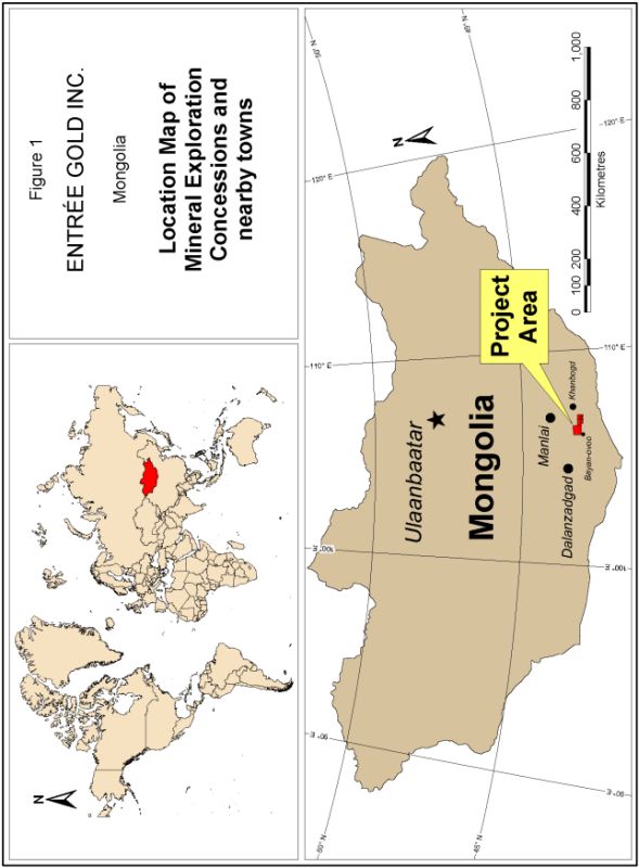
Note: Figure from
Panteleyev, 2004b
17
ENTRÉE GOLD INC.
LOOKOUT HILL PROJECT, MONGOLIA
NI 43-101 TECHNICAL REPORT, JUNE 2009
|
Figure
4-2:
|
Lookout
Hill Project - Land Tenure
|
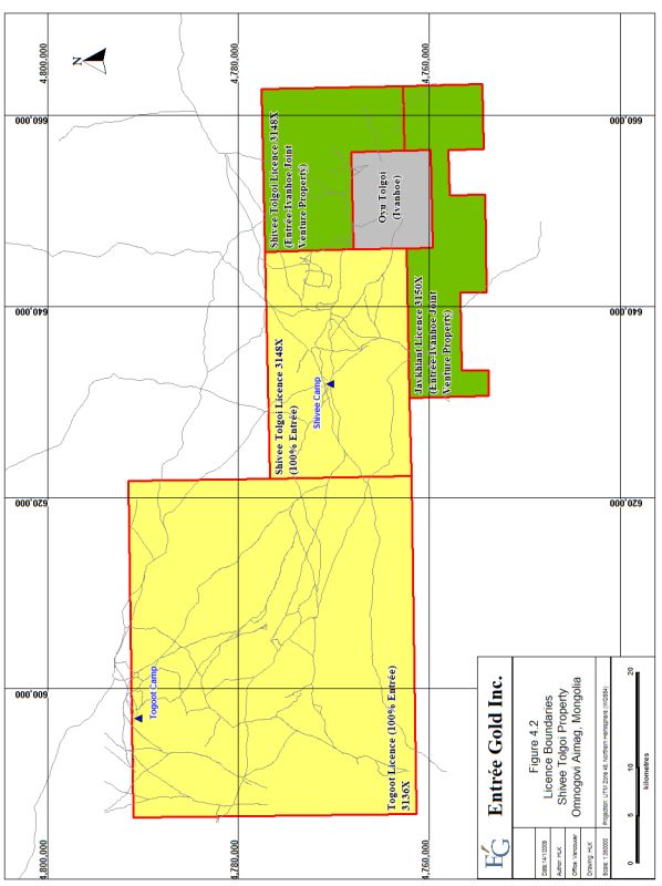
18
ENTRÉE GOLD INC.
LOOKOUT HILL PROJECT, MONGOLIA
NI 43-101 TECHNICAL REPORT, JUNE 2009
|
|
Entrée has
the right to require Ivanhoe to fund its share of subsequent joint venture
costs through to production, to be recovered from production cash
flow. Entrée will retain a 100% interest, subject to a right of
first refusal by Ivanhoe, in the remaining non-JV portion of Entrée’s
Shivee Tolgoi MEL and to the entirety of the Togoot
MEL. Currently Ivanhoe holds approximately 15% of Entrée’s
issued and outstanding shares.
|
|
|
The Shivee
Tolgoi JV Property is contiguous with, and on three sides (to the north,
east and south) surrounds, Ivanhoe’s Oyu Tolgoi Property and includes
19,518 ha over the eastern portion of the Shivee Tolgoi MEL and all of the
Javhlant MEL (20,346 ha). The details of the MELs within the JV
Property are shown in Table 4-2.
|
|
|
The
boundaries of the two MELs (or portions thereof) included within the JV
Agreement are defined by latitude and longitude coordinates and by UTM
coordinates with datum set to WGS-84, Zone 48N, and these are listed in
Table 4-2.
|
|
|
Table
4-2:
|
Shivee
Tolgoi JV Property Boundary
Coordinates
|
|
Lat./Long.
(MSK42; ° ‘ “)
|
UTM
(WGS84, Zone 48N)
|
||||
|
MEL
|
Point
|
Latitude
|
Longitude
|
Easting
|
Northing
|
|
3148X (Shivee
Tolgoi; eastern portion only)
|
1
|
43 08 00
N
|
106 47 30
E
|
645752.90
|
4777222.00
|
|
2
|
43 08 00
N
|
107 00 00
E
|
662698.13
|
4777605.65
|
|
|
3
|
43 00 00
N
|
107 00 00
E
|
663051.38
|
4762798.00
|
|
|
4
|
43 00 00
N
|
106 55 00
E
|
656258.54
|
4762639.53
|
|
|
5
|
43 03 00
N
|
106 55 00
E
|
656131.70
|
4768192.34
|
|
|
6
|
43 03 00
N
|
106 47 30
E
|
645950.77
|
4767967.25
|
|
|
3150X
(Javhlant)
|
1
|
43 00 00
N
|
106 36 00
E
|
630445.98
|
4762098.85
|
|
2
|
43 00 00
N
|
106 47 30
E
|
646069.34
|
4762414.47
|
|
|
3
|
42 58 30
N
|
106 47 30
E
|
646128.58
|
4759638.09
|
|
|
4
|
42 58 30
N
|
106 55 00
E
|
656321.92
|
4759863.13
|
|
|
5
|
43 00 00
N
|
106 55 00
E
|
656258.54
|
4762639.53
|
|
|
6
|
43 00 00
N
|
107 00 00
E
|
663051.38
|
4762798.00
|
|
|
7
|
42 55 30
N
|
107 00 00
E
|
663249.69
|
4754468.83
|
|
|
8
|
42 55 30
N
|
106 55 00
E
|
656448.59
|
4754310.38
|
|
|
9
|
42 57 30
N
|
106 55 00
E
|
656364.16
|
4758012.21
|
|
|
10
|
42 57 30
N
|
106 51 30
E
|
651605.97
|
4757905.31
|
|
|
11
|
42 55 30
N
|
106 51 30
E
|
651687.83
|
4754203.49
|
|
|
12
|
42 55 30
N
|
106 44 00
E
|
641486.25
|
4753985.55
|
|
|
13
|
42 57 00
N
|
106 44 00
E
|
641428.99
|
4756761.90
|
|
|
14
|
42 57 00
N
|
106 38 00
E
|
633271.07
|
4756598.47
|
|
|
15
|
42 55 30
N
|
106 38 00
E
|
633325.02
|
4753822.13
|
|
|
16
|
42 55 30
N
|
106 36 00
E
|
630604.62
|
4753769.81
|
|
|
Note:
|
Point 1 for
each MEL corresponds with the northwestern corner of the MEL; remaining
points are cited in a clockwise direction (see Figure
4-2).
|
|
4.2.2
|
Western
Mineral Exploration Licences (100%
Entrée)
|
The remaining MELs
cover 139,726 ha and include the western portion of the Shivee Tolgoi MEL
(35,242 ha) and all of the Togoot MEL (104,484 ha; Figure 4-2). These
MELs are held 100% by Entrée and are subject to the annual maintenance payments
as described in Section 4.2.3. These MELs have been renewed (Table
4-1), and final expiry is now in March and April of 2010, unless previously
converted to mining leases;
19
ENTRÉE GOLD INC.
LOOKOUT HILL PROJECT, MONGOLIA
NI 43-101 TECHNICAL REPORT, JUNE 2009
such a conversion
is dependent upon delineation of a Mineral Resource on each of the MELs and
approval of the Mongolian government. The boundaries of the two MELs
(or portions thereof) which are 100% held by Entrée are defined by latitude and
longitude coordinates and these are listed in Table 4-3.
|
|
Table
4-3:
|
Western
MELs (100% Entrée) Boundary
Coordinates
|
|
MEL
|
Lat./Long.
(MSK42; ° “ ‘)
|
||
|
Point
|
Latitude
|
Longitude
|
|
|
3148X (Shivee
Tolgoi; western portion only)
|
1
|
43 08 00
N
|
106 30 00
E
|
|
2
|
43 08 00
N
|
106 47 30
E
|
|
|
3
|
43 00 00
N
|
106 47 30
E
|
|
|
4
|
43 00 00
N
|
106 30 00
E
|
|
|
3136X
(Togoot)
|
1
|
43 16 00
N
|
106 04 00
E
|
|
2
|
43 16 00
N
|
106 30 00
E
|
|
|
3
|
43 00 00
N
|
106 30 00
E
|
|
|
4
|
43 00 00
N
|
106 04 00
E
|
|
|
|
Note:
|
Point 1 for
each MEL corresponds with the northwestern corner of the MEL and then
cited in a clockwise direction (see Figure
4-2).
|
|
4.2.3
|
Exploration
and Mining Title in Mongolia
|
|
|
Payments to
maintain mining and exploration MELs in Mongolia are payable in advance on
an annual basis according to the schedule shown in Table
4-4.
|
|
|
Table 4-4:
|
Exploration
and Mining Licence Annual Fees
|
|
Years
of Licence
|
Exploration
Licence
Cost
a Hectare
(US$)
|
Mining
Licence
Cost
a Hectare
(US$)
|
|
1
|
0.10
|
15.00
|
|
2
|
0.20
|
15.00
|
|
3
|
0.30
|
15.00
|
|
4
|
1.00
|
15.00
|
|
5
|
1.00
|
15.00
|
|
6
|
1.00
|
15.00
|
|
7
|
1.50
|
15.00
|
|
8
|
1.50
|
15.00
|
|
9
|
1.50
|
15.00
|
|
|
Note:
|
Beyond Year 9
of a mining licence, the licence fee remains $US15 a
hectare.
|
Prior to expiry of
the MEL, application can be made for conversion to a mining
licence. An MEL is valid for a three-year period and may be extended
for two additional three-year periods, giving a maximum nine-year
length. After nine years, the MEL must be converted to a mining
licence or it expires.
Royalties
potentially payable to the Mongolian government are governed by Article 47 of
the Minerals Law of Mongolia. Pursuant to the Minerals Law, the
Mongolian government assesses a royalty of 5% on the sale value of all minerals
mined in the country except gold extracted from placer, which is assessed at a
royalty rate of 7.5% of the sales value of such a mineral.
20
ENTRÉE GOLD INC.
LOOKOUT HILL PROJECT, MONGOLIA
NI 43-101 TECHNICAL REPORT, JUNE 2009
In May, 2006
Mongolia introduced new levies comprising a corporate income tax of 25% on
annual incomes over three billion tugrugs. In addition, a Windfall
Profits law imposes a higher incremental tax rate of 68%, when copper prices
reach US$2,600 per tonne ($1.18 per pound), and when gold reaches US$500 an
ounce.
|
4.2.4
|
Surface
Rights and Permits
|
|
|
Mongolian
Mining Law allows, through grant of the MELs, Entrée the right to access
and explore the area of the MELs subject to land use agreements and fees
with the local soums (districts).
|
|
4.2.5
|
Surveying
|
|
|
The MELs
within the Lookout Hill Project were legally surveyed in October, 2007 by
Aerogeodez from Ulaanbaatar and the corners marked with steel
posts. The adjacent Oyu Tolgoi Property was legally surveyed in
August 2002 by Surtech International Ltd. using the internationally
recognized survey datum WGS84 Zone 48N. In September 2004,
Geomaster Co. Ltd. (Geomaster), a licenced Mongolian land survey company,
re-surveyed the Oyu Tolgoi licence’s corner points based on the official
Mongolian survey datum “MSK42” and marked the corners with concrete and
steel pylons. In November 2004, Geomaster also surveyed the
northern boundary between the Oyu Tolgoi Property and Entrée’s Shivee
Tolgoi MEL and marked it with wooden posts on 250 m to 500 m
intervals.
|
|
4.2.6
|
Environmental
and Socio-Economic Issues
|
|
|
Entrée is
fully compliant with Mongolian exploration regulations. All
phases of the Company’s operations are subject to the Minerals Law of
Mongolia, Land Law and the Law on Environmental Protection as well as the
various Taxation Laws.
|
|
|
In Mongolia,
companies are required to file an annual exploration and environmental
plan with the local township or district (soum) governor’s offices and are
required to deposit 50% of the proposed reclamation budget which will be
refunded only on completion of acceptable land rehabilitation after
exploration or mining operations have concluded. The Entrée
Project is affiliated with two soums, Khanbogd and Bayan
Ovoo. The soums must also be paid for water and road
usage. Payments are computed at the end of each calendar year
based on the extent of use. Even if the Company relinquishes
its MELs, it remains responsible for any required
reclamation. Entrée states that at the time of this report, it
is in compliance with all environmental
requirements.
|
|
|
Once the
exploration phase is complete and Entrée requests the conversion of the
MEL to a Mining Licence, further environmental and social studies
obligations must be completed in the form of an environmental impact
assessment and an environmental protection
plan.
|
|
|
There are few
inhabitants living within the boundaries of the Property and no towns or
villages of significant size. The people who do live there are mostly
nomadic herders.
|
21
ENTRÉE GOLD INC.
LOOKOUT HILL PROJECT, MONGOLIA
NI 43-101 TECHNICAL REPORT, JUNE 2009
|
|
Entrée is
currently engaged in a small program of basic infrastructure improvements
to assist the nearby communities in the vicinity of the
Project. In addition, Entrée maintains close contact with the
district soums as part of their community relations
efforts.
|
22
ENTRÉE GOLD INC.
LOOKOUT HILL PROJECT, MONGOLIA
NI 43-101 TECHNICAL REPORT, JUNE 2009
|
5.0
|
ACCESSIBILITY,
CLIMATE, LOCAL RESOURCES, INFRASTRUCTURE, AND
PHYSIOGRAPHY
|
|
|
|
5.1
|
Accessibility
|
|
|
The city of
Ulaanbaatar has the nearest international airport to the Property with
regularly scheduled commercial flights from various Asian
destinations. The flying times from Seoul, Korea and Beijing,
China to Ulaanbaatar are about 2.5 and 1.5 hours,
respectively. Access to the Project by road is possible year
round; however, the unpaved road is in poor condition. Short
periods of no road access can occur, due to frequent heavy winds and dust
storms, or more rarely, snowstorms in the winter. The driving
time for the 630 km trip by four-wheel drive truck from Ulaanbaatar, via
Mandalgovi or Choyr to the site is approximately ten to twelve
hours.
|
|
|
Alternatively,
access is possible by air, via turbo prop charter aircraft to Ivanhoe’s
private 2200 m gravel landing strip at the adjacent Oyu Tolgoi
site. Although the air strip is designated for use by Ivanhoe,
Entrée personnel are permitted to occasionally use the charter aircraft to
arrive at the site. One to three times per week the air strip
receives turbo prop charters from Ulaanbaatar. Flying time from
Ulaanbaatar is approximately 1.5
hours.
|
|
5.2
|
Climate
|
|
|
The southern
Gobi region has a continental, semi-desert climate with cool springs and
autumns, hot summers, and cold winters. The average annual
precipitation is approximately 80 mm, 90% of which falls in the form of
rain with the remainder as snow. Snowfall accumulations rarely
exceed 50 mm. Maximum rainfall events of up to 43 mm have been
recorded for short-term storm events. In an average year, rain
falls on only 25 to 28 days and snow falls on 10 to 15
days. Local records indicate that thunderstorms are likely to
occur between two and eight days a year at the project area, with an
average total of 29 hours of electrical activity annually. An
average storm will have up to 83 lightning flashes a
minute.
|
|
|
Temperatures
range from an extreme maximum of about 36°C to an extreme minimum of about
-31°C. The air temperature in wintertime fluctuates between
-5°C and -31°C. In the coldest month, January, the average
temperature is -12°C.
|
|
|
Wind is
usually present at the site. Very high winds are accompanied by
sand storms that often severely reduce visibility for several hours at a
time. The records obtained from nine months of monitoring at
the Oyu Tolgoi project weather station show that the average wind speed in
April is 5.5 m/s. However, windstorms with gusts of up to
40 m/s occur for short periods. Winter snowstorms and
blizzards with winds up to 40 m/s occur in the Gobi region between
five and eight days a year. Spring dust storms are far more
frequent, and these can continue through June and
July.
|
|
5.3
|
Local
Resources and Infrastructure
|
|
|
There are a
number of communities in the south Gobi region. The most
prominent is Dalanzadgad (ca. 15,000 people),
which is the centre of the Omnogovi Aimag and located 220 km
west-northwest of the Project. Facilities at Dalanzadgad
include a
|
23
ENTRÉE GOLD INC.
LOOKOUT HILL PROJECT, MONGOLIA
NI 43-101 TECHNICAL REPORT, JUNE 2009
|
|
regional
hospital, tertiary technical colleges, a domestic airport, and a 6 MW
capacity coal-fired power station. The closest community to the
property is Bayan Ovoo (population 1,600), 5 km from the southwest corner
of the Project area. Other communities relatively near to the
project include Khanbogd (population 2,000), the centre of the
Khanbogd soum, 18 km to the east-northeast, Mandalgovi (population
13,500), which is capital of the Dundgovi Aimag and located 310 km north
of the project on the road to Ulaanbaatar, and Manlai (population 2,400),
150 km to the north (refer to Figure
4-1).
|
|
|
Although the
local towns can provide the most basic mining and exploration needs for
the early stages of exploration and project development (including basic
labour requirements, food and other supplies), the majority of
mining-related equipment and services for more advanced projects must be
obtained from Ulaanbaatar or other locations in
Asia.
|
|
|
Currently,
the Entrée onsite infrastructure comprises two field exploration camps
with basic sleeping facilities for approximately 60 people in tents
(locally referred to as gers) as well as kitchen, dining, bathroom and
shower facilities, recreational areas, offices, core logging, cutting and
storage areas. Office and core logging facilities are
Weatherhaven-style portable
buildings.
|
|
|
The
acquisition of the MELs also grants access to the land and to complete the
required exploration. Later, if a significant discovery is made
and a Mining Licence is granted, surface rights, sufficient for a mining
and processing operation will also be granted subject to applicable Land
and Environmental Protection laws. As part of the JV agreement,
Entrée has agreed to Ivanhoe having a long-term option to utilize surface
rights for future mining activities, including tailings storage, an
international airport and other
infrastructure.
|
|
|
The
Trans-Mongolian Railway, which crosses the Mongolia-China border
approximately 420 km east of the property, traverses the country from
southeast to northwest through Ulaanbaatar between Russia and
China. The Chinese government has upgraded 226 km of highway
from Gushaan Suhait to Wuyuan, providing a direct link between the
Mongolian border crossing, 80 km south of Oyu Tolgoi, and the Trans-China
Railway system (Figure 5-1). Ivanhoe reports that they have
entered into negotiations with Mongolian and Chinese government
authorities to extend the highway the final 80 km to the Oyu Tolgoi
project site.
|
24
ENTRÉE GOLD INC.
LOOKOUT HILL PROJECT, MONGOLIA
NI 43-101 TECHNICAL REPORT, JUNE 2009
|
Figure
5-1:
|
Transportation
Infrastructure
|
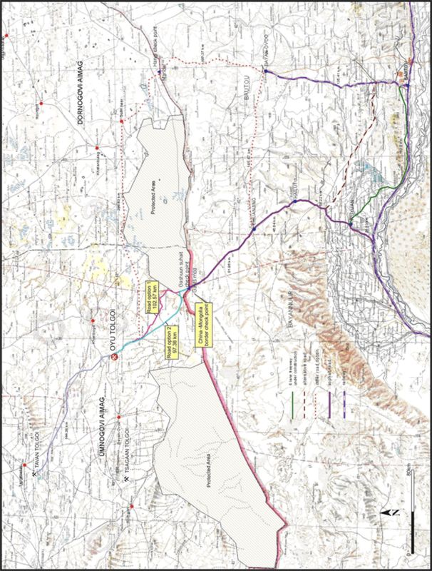
Note: Figure from Ivanhoe
Mines Ltd.
25
ENTRÉE GOLD INC.
LOOKOUT HILL PROJECT, MONGOLIA
NI 43-101 TECHNICAL REPORT, JUNE 2009
The Mongolian
government has previously conducted extensive exploration for water resources in
the south Gobi region, and a number of such resources were reportedly
discovered. Within the Project area, water is widely available from
shallow wells, and is sufficient for exploration purposes. Ivanhoe
has identified three deep sedimentary groundwater systems within 100 km of the
Oyu Tolgoi Project. Investigative drilling of two of these systems
and computer modeling of the systems has now been completed and indicates that
these groundwater systems will be able to meet the water demand for a production
rate of up to 40 million tones per year. The use of the water from
these systems is subject to finalization of the environmental impact assessment
(EIA) for the Oyu Tolgoi project and the issue of extraction licences by the
Mongolian government.
The nearest power
line is 350 km away from the Project site. Entrée currently use
generators for power for their camp, which is sufficient for this stage of
exploration activities. At the adjacent Oyu Tolgoi project, Ivanhoe
also operates a number of diesel generators for camp electrical needs; however
additional power sources will need to be developed prior to the commencement of
mine development and mining operations.
|
|
Based on the
results of an Integrated Development Plan (IDP) completed in 2005
(AMEC-Ausenco, 2005; Hodgson et al., 2005), the most
cost-effective and reliable power supply for future production at the
adjacent Oyu Tolgoi Project is considered to be the combination of a
coal-fired power station at the currently undeveloped Tavan Tolgoi coal
property 140 km northwest of the site, in conjunction with a 220 kV
transmission line connection to the substantial power grid in Inner
Mongolia. This could possibly also provide a power source for
any future production at the Hugo North
Extension.
|
|
5.4
|
Physiography
|
|
|
The elevation
of the Lookout Hill Project ranges from 1115 to 1450 masl. The
topography varies from flat gravel-covered plains interspersed with fields
of plant-stabilized, hummocky sand dunes that are about a metre in height,
to rocky, rugged low hills and ridges that can reach 60 m in
height. Scattered, small rock outcrops and colluvial talus are
widespread within the northern, western, and southern parts of the
property.
|
|
|
Numerous
ephemeral streams cross the Project and flow for short periods immediately
after rainfall. Water is widely available from shallow wells,
while generally saline, the water is suitable for industrial uses such as
drilling.
|
|
|
The region is
covered by sparse semi-desert vegetation and is used by nomadic herders
who tend camels, goats, horses and
sheep.
|
|
5.5
|
Seismicity
|
|
|
Knight
Piésold completed a full seismic hazard assessment for Ivanhoe’s Oyu
Tolgoi property in 2004 and 2005 (AMEC-Ausenco, 2005; Juras,
2005). This assessment incorporated findings of a seismic
assessment completed by the Mongolian Research Centre for Astronomy and
Geophysics, Mongolian Academy of Sciences, in March
2005.
|
|
|
The
seismicity of eastern Mongolia is generally low. The nearest
known active seismo-tectonic zone to the project site is the Mongolian
Altai, approximately 500 km to 1000
km
|
26
ENTRÉE GOLD INC.
LOOKOUT HILL PROJECT, MONGOLIA
NI 43-101 TECHNICAL REPORT, JUNE 2009
|
|
to the
west-northwest. Probabilistic and deterministic methods of
analysis of available data concluded that the seismic risk for the Oyu
Tolgoi project is low; by analogy, the risk for the Lookout Hill Project
is also low.
|
27
ENTRÉE GOLD INC.
LOOKOUT HILL PROJECT, MONGOLIA
NI 43-101 TECHNICAL REPORT, JUNE 2009
|
6.0
|
HISTORY
|
|
6.1
|
Introduction
|
|
|
Mining
legislation that was drafted in Mongolia in the early to mid-1990s sparked
exploration of the southern Gobi region in what became known as the ‘South
Mongolian (porphyry) copper-gold belt’. The area was evaluated
by a number of companies, including Magma Copper Company, which, in 1995,
targeted the area of the Oyu Tolgoi deposits. Following a
corporate takeover, the work by Magma was continued by BHP Exploration
Ltd. By 1999, a significant copper-gold resource had been
identified at Oyu Tolgoi (Perelló et al.,
2001). At the end of this period, Ivanhoe acquired BHP’s
interest in the Oyu Tolgoi
property.
|
|
|
During the
period 1996-1999, BHP also conducted preliminary geological investigations
and some reconnaissance geophysical work in other areas, including areas
within the Lookout Hill Project. The three MELs that comprise
the Project were acquired by a private Mongolian group (Mongol Gazar) in
March and April 2001, who subsequently completed grid surveying, soil
sampling and shallow gradient-type IP geophysical surveys. This
work was primarily in the area of Zones I and III in the western portion
of the Shivee Tolgoi MEL.
|
|
|
The property
was first optioned from Mongol Gazar by Entrée in July 2002 and later 100%
interest was purchased. Entrée initially focused on Zones I,
II, III and on the copper showings near Bayan Ovoo. Other areas such as
Ring Dyke and West Grid were targeted based on results from ground
geophysical surveys (magnetometer and IP surveys), mapping, rock and soil
geochemical sampling, reverse-circulation and core
drilling. The Shivee Tolgoi MEL was the focus of most of the
work until 2008 when Togoot MEL was the primary
target.
|
|
|
These areas
as well as those of prior exploration campaigns are shown in Figure 6-1
below. The earlier exploration programs are covered in detail
in previous technical reports on SEDAR (e.g. Cann, 2004;
Cherrywell, 2005; Panteleyev, 2005; Vann et al.,
2008).
|
|
6.2
|
Shivee
Tolgoi JV Property
|
|
|
In late 2002,
drilling by Ivanhoe in the far northern section of the adjacent Oyu Tolgoi
Property had intersected 638 m of bornite-chalcopyrite-rich mineralization
in OTD-270 and marked the discovery of the Hugo Dummett Deposit. As
exploration continued to the north it appeared that the Hugo North Deposit
might extend onto the Shivee Tolgoi MEL and in October 2004 Entrée entered
into an Earn-In Agreement with Ivanhoe in which Ivanhoe was the
operator. Details of the discovery of the Hugo North Extension
Deposit on the Shivee Tolgoi MEL and the drilling that that supports the
current resource can be found in the March 2007 technical report (Cinits
and Parker, 2007).
|
28
LOOKOUT HILL PROJECT, MONGOLIA
NI 43-101 TECHNICAL REPORT, JUNE 2009
|
Figure
6-1:
|
2002
- 2008 Exploration Areas, Shivee Tolgoi
Property
|

29
ENTRÉE GOLD INC.
LOOKOUT HILL PROJECT, MONGOLIA
NI 43-101 TECHNICAL REPORT, JUNE 2009
|
|
Prior to the
agreement between Entrée and Ivanhoe in 2002-2004, Entrée mapped,
prospected, completed extensive soil sampling and conducted IP, gravity
and magnetometer surveys over the area immediately north of the
Entrée-Ivanhoe property boundary. After signing the agreement,
all work was conducted by Ivanhoe, the project
operator.
|
|
|
On the
Javhlant MEL, Ivanhoe began drill testing chargeability anomalies for deep
mineralization similar to that in the Hugo North deposits and the Oyu
South deposits in March 2007. Copper, gold and molybdenum
mineralization was intersected in a number of holes but an intercept of
501.2 m of 0.50% Cu, 0.29 g/t Au and 182 ppm Mo in EJD0008 indicated the
significant potential in this area. As geological understanding of the
deposit increased, it was clear that early, weakly-mineralized holes at
the north end of the deposit were too shallow and subsequent deepening of
these holes confirmed mineralization continued but deepened to the
north. Since February 2008, 14 drillholes have targeted the
western, southwestern and northern ends of the Heruga Deposit. Additional
drilling is planned within the main Heruga Ore zone to complete the
initial Inferred pattern. Once this is complete in 2009, Ivanhoe intends
to update the Heruga resource estimate. Approximately five holes are still
outstanding to complete the
pattern.
|
|
6.3
|
Western
MELs (100% Entrée)
|
|
|
There are
small pits and trenches of possible Bronze Age on the Togoot MEL that
expose copper-oxide mineralization. However, the writers are
unaware of any significant exploration activity leading to drilling prior
to Entrée’s acquisition of the Shivee Tolgoi
Property.
|
|
|
In the early
to mid-1990s, changes to Mongolian mining law ushered in a period of
exploration for porphyry copper-gold deposits. By 1999, first
Magma Copper then BHP had outlined a significant copper-gold resource of
438 Mt, averaging 0.48% copper and 0.25 g/t gold at Oyu Tolgoi (Perelló
et al., 2001;
note that this historical estimate pre-dates and is not necessarily in
accordance with resource classification categories of NI
43-101).
|
|
|
In March and
April 2001, a private Mongolian company, Mongol Gazar, acquired
the three MELs comprising the Lookout Hill Project and
undertook grid surveying, soil sampling and shallow gradient-type IP
geophysical surveys. This work was for the most part confined
to an area northwest of Oyu Tolgoi that featured epithermal-style
alteration which would eventually become Zones I and
III.
|
|
|
Entrée began
exploring the Project in July 2002, and acquired the property outright
from Mongol Gazar in November 2003. Field work during these two
years included prospecting, soil geochemical sampling of seven separate
areas, chip sampling and some orientation silt and pan concentrate
sampling in selected areas. Five areas were subject to 239.2
line-km of pole-dipole IP surveying, and 255.8 line-km of magnetometer
surveying. Gravity surveying (85.1 line-km) was carried out
over the Copper Flats Grid located north of the Oyu Tolgoi Property, and
on selected lines over Main Grid Zones I and II. Geological
mapping was done at 1:2000 scale over the Main Grid Zone III, 1:5000 scale
over X-Grid (Oortsog, east of Oyu Tolgoi), and 1:10000 scale on
the
|
30
ENTRÉE GOLD INC.
LOOKOUT HILL PROJECT, MONGOLIA
NI 43-101 TECHNICAL REPORT, JUNE 2009
|
|
Copper Flats
Grid. Three trenches totalling 546 m were excavated on Main
Grid Zone III.
|
|
|
Follow-up
work during 2004 comprised ground geophysical surveys and initial diamond
drill testing of selected targets; the main focus of work in this period
was concentrated on the Copper Flats grid that is now within the JV
Property. Entrée began diamond drilling (18 holes totaling
3931.85 m) on several targets including Zone I, Zone III and Oortsog (now
within JV Property) in 2004.
|
|
|
From
2005-2007 exploration on the property included satellite image
interpretation, reconnaissance exploration, geophysical surveys (IP and
airborne and ground mag), detailed geological mapping, rock sampling, soil
and MMI sampling, trenching, diamond and reverse-circulation
drilling. Airborne magnetometer and radiometrics surveys were
flown by Geosan in 2007 over the entire licence, which ultimately led to
target selection for the 2008 field season. Details on the
earlier exploration can be found in previous technical reports (Cann,
2004; Cherrywell, 2005; Panteleyev, 2005) and are on SEDAR. The
focus of the 2008 program was coal exploration on the northwestern area of
the Togoot licence (Nomkhon Bohr, Coking Flats, Khar Suul), and copper,
gold, and molybdenum on Altan Khulan, Tom Bogd, Ukhaa Tolgod, Baruun
Khatnii Guya and Ring Dyke (Figure 6.1). Further information on the 2008
exploration and drilling programs are contained in Section 10
(Exploration) and Section 11
(Drilling).
|
31
ENTRÉE GOLD INC.
LOOKOUT HILL PROJECT, MONGOLIA
NI 43-101 TECHNICAL REPORT, JUNE 2009
|
7.0
|
GEOLOGICAL
SETTING
|
|
|
Mongolia is
underlain by the Central Asian Orogenic Belt, sandwiched between the
Siberian Craton on the north and the Tarim and Sino-Korean Cratons to the
south. The belt is characterized by numerous accreted terranes
(Badarch et al.,
2002). An arcuate lineament, the Main Mongolian Lineament,
divides the country into two domains. To the north is a domain
of Precambrian to Paleozoic metamorphic rocks, Lower Paleozoic ophiolites
and island arc volcanics usually classified as a Caledonian orogen
(Badarch, 2005). The southern domain comprises Lower to Middle
Paleozoic arc volcanics and volcaniclastics, a Hercynian (or Variscan)
orogen. Fault-bounded basins of Upper Jurassic to Cretaceous
continental volcanic and sedimentary rocks overlie the eastern portions of
both domains.
|
|
|
The Central
Asian Orogenic Belt records a complex history of Paleozoic tectonics and
magmatism related to terrane accretion along the northern margin of the
Paleo-Asian Ocean above a generally-interpreted north-dipping subduction
zone (Blight et
al., 2008). Closure of the ocean was completed in the
Permian. Subsequently, a number of periods of deformation
during the Mesozoic affected Mongolia, including Triassic to Cretaceous
strike-slip faulting, Jurassic thrust faulting, and Jurassic to Cretaceous
crustal extension.
|
|
7.1
|
Regional
Geology
|
|
|
The Western
Licences lie within the middle to late Paleozoic Gurvansayhan Terrane, an
island-arc terrane accreted to the back-arc Gobi Altai terrane to the
north (Figure 7.1). Badarch et al., 2002
describe the Gurvansayhan terrane as being “...composed of dismembered
ophiolite, melanges, Ordovician - Silurian greenschist facies
metamorphosed sandstones, argillite, chert, volcaniclastic rocks, Upper
Silurian - Lower Devonian radiolarian chert, tholeiitic pillow basalt,
andesite, tuff, Middle Devonian - Mississippian volcaniclastic rocks,
chert containing Frasnian conodonts, and minor olistostrome with coral
limestone clasts…The major- and trace-element characteristics of Devonian
basalt indicate volcanism in an arc environment...The terrane contains
porphyry copper deposits, such as Tsagaan Suvarga and Oyu Tolgoi...The
structure of the terrane is complex and dominated by imbricate thrust
sheets, dismembered blocks , melanges, and high strain
zones. There are several melange zones containing blocks of
pillow lavas, fossiliferous limestone, sandstone, gabbro, diabase dykes,
and amphibolite. On the southeastern margin of the terrane is
located the Hanbogd riebeckite-richorbicular granite pluton...The terrane
is overlain by Carboniferous, Permian, Jurassic and Cretaceous volcanic
and sedimentary rocks.” Lamb and Badarch (2001) suggest two
possibilities for the tectonic setting: an island arc “… perhaps built on
the outer edge of the sedimentary prism of a continental shelf…” or a
“…continental arc that changed along strike to an island
arc.”
|
32
ENTRÉE GOLD INC.
LOOKOUT HILL PROJECT, MONGOLIA
NI 43-101 TECHNICAL REPORT, JUNE 2009
|
Figure
7-1:
|
General Geology of Mongolia (after
Badarch et
al.,
2002)
|

33
ENTRÉE GOLD INC.
LOOKOUT HILL PROJECT, MONGOLIA
NI 43-101 TECHNICAL REPORT, JUNE 2009
|
|
Carboniferous
rocks indicate the continuation of volcanism after the Devonian, with
development of a more continental back-arc basin (Lamb and Badarch, 2001)
featuring subaerial intermediate to felsic volcanic
centres. Uplift and unroofing of Devonian granitic rocks is
indicated by the presence of coarse granitic boulders in cobble and
boulder conglomerates.
|
|
|
Permian
strata in southern Mongolia comprise fluvial depositional environments
(Lamb and Badarch, 2001) in the southwest and marine turbidite flysch
deposits in the southeast. Arc volcanism had ceased, but
tectonic activity continued, with continental volcanism possibly related
to the consolidation of Central
Asia.
|
Mesozoic and
Cenozoic lacustrine sedimentary basins are built on top of the accreted
Paleozoic terranes (Hendrix et
al., 2001). A mountain chain representing the final stage of
Carboniferous-Permian accretion provided the source for Triassic to mid-Jurassic
sedimentary rocks, confined to intermontane basins and foreland
settings. Triassic rocks are generally conglomerates, coarse
sandstones and felsic volcanics (Traynor and Sladen, 1995). The Late
Cretaceous to Cenozoic clastic sedimentary rocks infilled older topography,
during a time of compressional tectonics.
|
|
Changing
climatic conditions are indicated by the regional facies relationships
established during accretion of Paleozoic terranes. Two
transitions occur: 1) a shift from arid to humid setting in the
mid-Permian, evidence for this being redbed sandstones representing
well-drained soils and oxidizing conditions underlying Upper Permian
coal-bearing strata; and 2) coal-bearing Upper Permian strata overlain by
Lower Triassic sandstones, coinciding with the great extinction event at
the Permian-Triassic boundary.
|
|
7.2
|
Shivee
Tolgoi JV Property
|
|
7.2.1
|
Hugo
North Extension
|
The Hugo North
Extension Deposit occurs within a geological setting similar to that at Hugo
North within the Oyu Tolgoi mining lease. Host rocks are an
easterly-dipping sequence of volcanic strata correlated with the lower part of
the Devonian Alagbayan Formation and quartz monzodiorite intrusive rocks. The
geological setting was established through work completed prior to 2008 and is
described in more detail in the March 2008 technical report (Vann et al., 2008). The
host rocks descriptions below are taken from Blower (2006). Note that
in Blower (2006), the deposit was discussed under the former name of Copper
Flats; this report uses the current Hugo North Extension nomenclature and uses
the Copper Flats name only for the exploration grid.
|
|
The Devonian
stratified host rock sequence in the Hugo North Extension Deposit dips
moderately (65° - 75°) to the east or southeast, except for a
structurally-induced strike flexure in the southern part of the deposit,
within which dips are southward.
|
|
|
These strata
include the lower, strongly-altered augite basalt and dacite tuff sequence
(units DA1 and DA2) overlain successively by weakly-altered, to unaltered
dacitic volcanic conglomerate and breccia (unit DA2), mudstone and
siltstone (unit DA3), and interstratified basaltic flows, breccias, and
epiclastic rocks (unit DA4). The contact between units DA3 and
DA4 is a bedding-parallel fault, and the original stratigraphic
relationship between unit DA4 and the underlying units is
uncertain. Figure 7-2
presents
|
34
ENTRÉE GOLD INC.
LOOKOUT HILL PROJECT, MONGOLIA
NI 43-101 TECHNICAL REPORT, JUNE 2009
the current
stratigraphic understanding for the Oyu Tolgoi deposits, including Hugo North
Extension. Detailed descriptions of the rock units can be found in
the March 2008 technical report (Vann et al., 2008). A geological
plan is shown in Figure 7-3.
Sedimentary
and Volcanic Rocks
Devonian
Alagbayan Formation
The oldest rocks
identified are correlated with the Upper Devonian Alagbayan
Formation. Four major lithologic divisions are present within the
Alagbayan Formation, and each of these divisions comprises two or more subunits
that can be readily mapped. The two lower units are commonly strongly
altered and form important mineralization hosts, while the upper two units,
although pre - to syn-mineral in age, lack significant alteration, and
mineralization.
Unit
DA1: Basaltic Flows and Volcaniclastic Rocks
The
stratigraphically lowest rocks identified to date at Shivee Tolgoi consist of
mafic volcanic flows and volcanogenic sedimentary rocks, forming a sequence at
least several hundred of metres thick. These rocks are commonly
strongly altered and host much of the contained copper in the Hugo North
Extension Deposit.
Unit
DA2: Dacite Tuff - Volcaniclastic Rocks
Volcanic fragmental
rocks of dacitic composition overlie the basaltic rocks of unit
DA1. The dacite sequence can be up to 200 m thick and consists of two
major divisions. Volumetrically dominant is buff to dark green,
dacite lapilli tuff with common eutaxitic texture and ovoid to globular
fragments. This subunit occurs in the lower part of the sequence and
is usually overprinted by intense sericite and advanced argillic
alteration. It is overlain by or partially interstratified with a
thinner unit of typically unsorted, polymictic block tuff to
breccia. This coarser subunit is usually less altered than the
lapilli tuff and does not contain significant copper
mineralization.
|
|
A zircon U/Pb
date of 365±4 Ma constrains the age of the dacite sequence to Upper
Devonian (Wainwright et
al., 2005).
|
35
ENTRÉE GOLD INC.
LOOKOUT HILL PROJECT, MONGOLIA
NI 43-101 TECHNICAL REPORT, JUNE 2009
|
Figure 7-2:
|
Stratigraphic
Column, Oyu Tolgoi Exploration Area
|
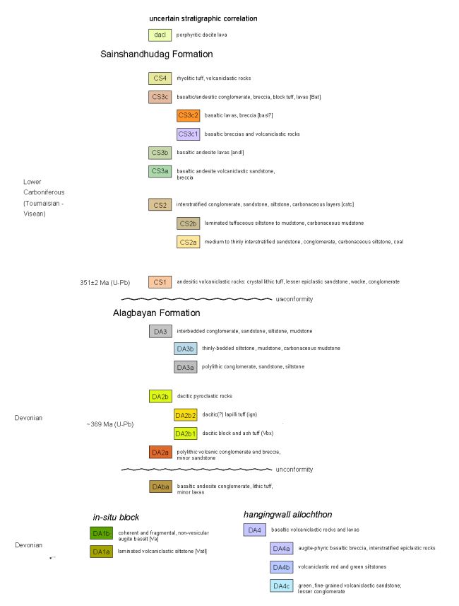
Note: Figure
from Lewis, 2008
36
LOOKOUT HILL PROJECT, MONGOLIA
NI 43-101 TECHNICAL REPORT, JUNE 2009
|
Figure
7-3:
|
Surface
Geology Map Shivee Tolgoi JV Property Showing Hugo North Extension and
Ulaan Khud
|

Note:
Figure from Ivanhoe Mines Ltd.
37
ENTRÉE GOLD INC.
LOOKOUT HILL PROJECT, MONGOLIA
NI 43-101 TECHNICAL REPORT, JUNE 2009
Intrusive
Rocks
|
|
Intrusive
rocks are widely distributed throughout the area and range from large
batholithic intrusions to narrow discontinuous dykes and
sills. At least seven classes of intrusive rocks can be defined
on the basis of compositional and textural
characteristics. Copper-gold porphyry mineralization is related
to the oldest recognized intrusive suite, comprising large Devonian quartz
monzodiorite intrusions. Many of the older intrusive units
found on the property are strongly to intensely-altered (e.g. quartz
monzodiorite suite), and the compositional classifications used for these
units should therefore be considered only as field
terms.
|
|
|
The
post-mineral intrusions include rhyolitic, hornblende-biotite andesite,
dacite, and basalt-dolerite compositional varieties. These
intrusions usually occur as dykes with subvertical orientations or less
commonly as easterly-dipping sills emplaced along stratigraphic
contacts. They are non-mineralized and not volumetrically
significant in most of the deposit.
|
Biotite
Granodiorite
Late - to
post-mineral biotite granodiorite intrusions form a voluminous
northerly-striking dyke system along the western side of the Hugo North
Extension Deposit and more-restricted dykes and sills elsewhere. The
intrusions are compositionally and texturally varied and probably include
several intrusive phases. Typically, they contain large plagioclase
phenocrysts with lesser small biotite phenocrysts, within a fine-grained to
aphanitic brown groundmass. The age of the biotite granodiorite is
constrained by U/Pb dating of zircon to 362 ± 4 Ma (Wainwright et al., 2005).
|
|
At levels
above approximately 250 m, where it cuts through the non-mineralized
hanging wall strata, the biotite granodiorite occurs as a single intrusive
mass with contacts dipping moderately to steeply to the
west. Below this level, the biotite granodiorite is more
complex, occurring as multiple, subparallel to anastomozing dykes that cut
through the quartz monzodiorite intrusion and mineralized Alagbayan
Formation strata.
|
|
|
The biotite
granodiorite intrusions locally contain elevated copper grades adjacent to
intrusive contacts or associated with xenolithic zones; however, they are
essentially non-mineralized.
|
Quartz
Monzodiorite
Porphyry-style
mineralization at the Hugo North Extension and Oyu Tolgoi deposits is
genetically linked to Late Devonian quartz monzodiorite to monzodiorite
intrusions, which form the most voluminous intrusions in the deposit
area. These intrusions are texturally and compositionally varied, and
several distinct phases can be distinguished within the
deposits. They are typically phenocryst-crowded, with >40%
plagioclase phenocrysts up to 5 mm long, and 10% to 15% biotite and
hornblende. Preliminary U/Pb zircon ages of 370.6 Ma and 378 Ma have
been obtained from unaltered and altered phases of the quartz
monzodiorite. These dates are at odds with the younger ages obtained
from the dacite tuff country rocks and require further analysis (Wainwright
et al.,
2005).
38
ENTRÉE GOLD INC.
LOOKOUT HILL PROJECT, MONGOLIA
NI 43-101 TECHNICAL REPORT, JUNE 2009
|
|
Quartz
monzodiorite contacts are irregular, but overall show a preferred easterly
dip, subparallel to stratification in the enclosing rocks. The
quartz monzodiorite is contemporaneous with alteration and mineralization,
and several varieties are distinguished on the basis of alteration
characteristics and position within the deposit: an intensely
quartz-veined phase; a gold-rich phase, restricted to the western part of
the main intrusion in the Hugo North Extension Deposit; and the main
intrusive body, which typically has lower vein density and lower copper
and gold grades. Cross-cutting relationships between the
different phases are ambiguous, and it is uncertain whether they represent
a temporally distinct intrusive events or simply variations in alteration
intensity related to position within the
deposit.
|
Structural
Geology
|
|
The Shivee
Tolgoi JV Property area Figure 7-3 is underlain by complex networks of
faults, folds, and shear zones. Most of these structures are
poorly exposed on surface and can only be defined through integration of
detailed exploration data (primarily drillhole data), property-scale
geological mapping, and geophysical data. Ivanhoe has made
extensive use of oriented core drilling, and the structural data collected
has been invaluable in helping determine the subsurface morphology and
structural history of both the Oyu Tolgoi deposits and the Hugo North
Extension Deposit. Major structures strongly influence the
distribution of mineralization by both controlling the original position
and form of mineralized bodies, and modifying them during post-mineral
deformation events.
|
|
|
The Hugo
North Extension Deposit occurs within moderately east dipping (65° to 75°)
strata contained in a north-northeasterly-elongate fault-bounded
block. The deposit is cut by several northeast-striking faults
and fault splays near the boundary with Oyu Tolgoi. Other than
these northeasterly faults, the structural geometry and deformation
history of the Hugo North Extension Deposit is similar to that of the Hugo
North Deposit.
|
|
|
Deformation
of the Hugo North Extension Deposit is dominated by brittle
faulting. Major faults cutting the deposit can be grouped on
the basis of orientation into three sets: steep north-northeast-striking
faults (West Bat); north-northeast-striking, moderate to steeply
east-dipping faults subparallel to lithologic contacts (Contact Fault);
and the east-northeast-striking faults cutting across the strike of the
deposit (Boundary Fault System).
|
|
|
7.2.2
|
Ulaan
Khud Prospect
|
The geology of this
area was established prior to 2008 through sterilization drilling, in
conjunction with surface mapping and is described in detail in Vann et al. (2008). In
2008 one additional hole was drilled but the interpretation has not
changed. The Ulaan Khud Prospect (also known as the Airport North
area) is 8 km to the north of the Entrée-Ivanhoe concession boundary (Figure
7-3).
|
|
7.2.3
|
Heruga
Deposit
|
|
|
Outcrop is
generally sparse on Javhlant MEL and much of the known geology is
extrapolated from more detailed geology available on Oyu Tolgoi to the
north, on geophysical interpretation (IP and detailed magnetics), and on
drill core where available.
|
39
ENTRÉE GOLD INC.
LOOKOUT HILL PROJECT, MONGOLIA
NI 43-101 TECHNICAL REPORT, JUNE 2009
|
|
The geology
of Oyu Tolgoi has been described in detail by Blower (2006) and by Cinits
and Parker (2007).
|
|
|
Parts of the
following sections are summarized and paraphrased from unpublished texts
provided to QG by Peter Lewis (Lewis Geoscience Services Inc.) and David
Crane (Senior Geologist for Ivanhoe). Review of core and
geological interpretations on site by QG indicated that the present
understanding of geology is reasonable given the generally wide drill
spacing.
|
Host
Rocks
|
|
Most of the
stratigraphic sequence in the Heruga Deposit is interpreted to be
equivalent to that documented in the Southern Oyu Tolgoi and Hugo Dummett
deposits (see preceding sections of this report). There are,
however, several stratigraphic relationships preserved at Heruga that led
Lewis (2008) to propose a revised stratigraphic column - specifically to
the sequence immediately overlying the Devonian
unconformity.
|
Devonian
Sedimentary and Volcanic Rocks
|
|
Based on
relationships observed in core at both the Heruga and more northerly Oyu
Tolgoi deposits, Lewis (2008) divides unit DA2 into three subunits (Figure
7-4):
|
|
|
•
|
DA2b1 and
DA2b2 represent
pyroclastic deposits of dacitic composition, corresponding to lithotypes
traditionally referred to as “dacitic block & ash tuff” and “dacitic
ash flow tuff” respectively. In most areas DA2b1 occurs lower
in section and these two units are distinguished from each other by clast
size, and by the common occurrence of large, quartz-phyric juvenile clasts
in DA2b1.
|
|
|
•
|
Unit
DA2a is
reserved by Lewis (2008) for the polylithic volcanic conglomerates lacking
a pyroclastic component. Drillholes containing all three
subunits of the DA2 sequence are rare, and any of the three may directly
overlie the Devonian unconformity. In drillholes where the
stratigraphic relationships between these divisions are preserved, unit
DA2a occurs below the pyroclastic rocks of unit
DA2b.
|
|
|
Lewis (2008)
also proposes a new unit in the Alagbayan Formation, ‘Unit
DAba’. Drillhole EJD-0012 at Heruga intersects a thick sequence
of basaltic to andesitic volcaniclastic rocks consisting of breccia to
conglomerate with pebble to cobble-sized
fragments. Monolithologic blocky breccias representing
flow-banded lavas or subvolcanic intrusions occur locally in this
sequence. To date, drillholes at Heruga have only intersected
this unit on the west side of the Bor Tolgoi Fault. Otherwise
the stratigraphy is as described
previously.
|
Intrusives
Biotite
Granodiorite
Biotite
granodiorite at Heruga intrudes Devonian rocks as it does throughout the Oyu
Tolgoi region. According to Forster et al. (2008) it occurs only
below the unconformity at Heruga, where it commonly forms sills intruding along
bedding-parallel structures near the Contact Fault. It also occurs
less commonly as sub-vertical dykes.
40
ENTRÉE GOLD INC.
LOOKOUT HILL PROJECT, MONGOLIA
NI 43-101 TECHNICAL REPORT, JUNE 2009
Quartz
Monzodiorite
|
|
Quartz
monzodiorite at Heruga is similar to that at the Southern Oyu Tolgoi and
Hugo Dummett deposits. The quartz monzodiorite at Heruga is
relatively fine grained and may possibly be present at two distinct phases
(one mineralized and one unmineralized). Much of the higher
grade portion of the deposit is localized adjacent to contacts of the
mineralized quartz monzodiorite intrusion. The interpretation
of Lewis (2008) shows clearly that this intrusion is nearly confined to a
single section at current drill spacing, indicating that its contacts are
nearly section parallel. QG concur with Lewis (2008) that any
infill drilling will require specific holes drilled perpendicular to
cross-section to better define its
geometry.
|
Andesite
and Dacite Dykes
Post-mineralization
porphyritic hornblende-biotite dykes of andesitic to dacitic composition are
widespread at Heruga and strike north to north east, dipping
steeply. Forster et
al. (2008) report that these dykes are similar to those dated as
Carboniferous in the Oyu Tolgoi deposits.
Basalt
and Rhyolite Dykes
Fine grained
basaltic dyke, interpreted as often intruding both steep and low-angle
structures (Forster et
al., 2008) are common at Heruga. These dykes also post-date
mineralization and are interpreted as coeval with similar dykes assumed to be
Carboniferous in the Oyu Tolgoi deposits. Rhyolite dykes are
relatively uncommon. Forster et al. (2008) note that some
dolerite dykes of possibly Mesozoic age are encountered at Heruga.
Structural
Geology
Heruga lies at the
southern end of a 20 km north-north-easterly trend of porphyry style deposits,
extending to Shivee Tolgoi (Hugo North Extension) in the
north. Forster et
al. (2008) postulate that this alignment reflects deep crustal structure,
exploited by Late Devonian magmatism and mineralizing systems.
|
|
The
interpretation of Lewis (2008) shows Heruga cut by several major brittle
fault systems, partitioning the deposit into discrete structural
blocks. Internally, these blocks appear relatively undeformed,
and consist of southeast-dipping volcanic and volcaniclastic
sequences. The stratiform rocks are intruded by quartz
monzodiorite stocks and dykes that are probably broadly contemporaneous
with mineralization, as well as sub-vertical hornblende-biotite andesite
dyke swarms discussed in the preceding section of this
report.
|
|
|
The
deposit-scale faults identified at Heruga displace mineralized zones, with
mineralization and alteration zones apparently not localized by the
faults, implying they post-date mineralization. Lewis (2008)
concludes that it is likely the Heruga porphyry formed within a relatively
intact structural block, with most faulting and disruption of contacts
related to post-mineralization
deformation.
|
41
ENTRÉE GOLD INC.
LOOKOUT HILL PROJECT, MONGOLIA
NI 43-101 TECHNICAL REPORT, JUNE 2009
|
Figure
7-4:
|
Geological
Plan of Heruga Deposit Area (Legend as in Fig.
7-2)
|

Note: Figure from Ivanhoe
Mines (2009).
Contact
Fault
|
|
As at Oyu
Tolgoi, volcaniclastic strata of unit DA4 are structurally juxtaposed over
the Heruga Deposit along a major, southeast-dipping fault
zone. Lewis (2008) describes this fault being “… almost
certainly the southerly extension of…” the Contact Fault at the Hugo
Dummett and Southern Oyu deposits.
|
42
ENTRÉE GOLD INC.
LOOKOUT HILL PROJECT, MONGOLIA
NI 43-101 TECHNICAL REPORT, JUNE 2009
|
|
The Contact
Fault at Heruga varies from tens of centimetres to 40 m in thickness, and
has an average orientation striking 110° and dipping 45° east
southeast. Lewis (2008) also reports that kinematic indicators
such as shear bands and drag folds record up-dip (thrust)
displacement.
|
|
|
In the
northern part of the deposit, facing direction reversals and repetition of
stratigraphic units define a large-scale recumbent anticline in the
hangingwall sequence to the Contact Fault. Although the
magnitude of displacement on the Contact Fault is poorly constrained, the
scale of the overturned folds in the hangingwall, vertical stacking of
dissimilar stratigraphic sequences, and the fault continuity throughout
the Oyu Tolgoi area all suggest that displacement of kilometres to tens of
kilometres is probable.
|
East-Northeast
Striking Bounding Faults
|
|
The Heruga
Deposit area lies between two regional, northeast-striking faults that
form prominent features on both magnetic and satellite
images. The northern (unnamed) fault crosses the deposit trend
approximately 300m north of the northernmost drillholes at the time of
writing. Lewis (2008) reports that this fault is not directly
exposed nor has it been intersected in drillholes. In
consequence, neither its dip direction nor its kinematic history are well
constrained.
|
|
|
The southern
bounding fault (‘South Sparrow Fault’) crosses the deposit trend
approximately 250 m south of the southern most drillhole at the time of
writing (EJD-0019). One drillhole has been completed in the
Heruga area south of this fault (EJD-0016) which intersected a thick
sequence of weakly-altered to unaltered volcaniclastic rocks of probable
Carboniferous age, suggesting south-side-down apparent
offset.
|
Bor
Tolgoi Fault System
|
|
Lewis (2008)
divides the Heruga Deposit into four discrete structural blocks by
subvertical, north-northeast-striking faults he refers to as the ‘Bor
Tolgoi Fault System’. These faults occur in drill core as
intervals of breccia and gouge, sighted by QG during the site visit, and
also reportedly form subtle linear anomalies on ground magnetic
images.
|
|
|
In east-west
sections, both the West Bor Tolgoi Fault and the better constrained Bor
Tolgoi Fault display between 300 m and 500 m west-side-down apparent
offset of stratigraphic contacts (Lewis, 2008). Kinematic
indicators have not been observed in either fault, and consequently the
true slip direction and magnitude are
unconstrained.
|
|
|
Lewis (2008)
interprets fault movement as dominantly
strike-slip.
|
Southern
Fault
|
|
The Southern
Fault is an interpreted steep, west-northwest-striking structure that cuts
across the southern end of the Heruga Deposit. Although
multiple interpretations are possible, Lewis (2008) concludes that the
simplest fault geometry compatible with the apparent offsets of contacts
in these drillholes requires only a single section-parallel
fault. Surface maps show an interpreted fault roughly
coincident with the interpreted structure, and the fault trace also
coincides with a weak linear magnetic
feature.
|
43
ENTRÉE GOLD INC.
LOOKOUT HILL PROJECT, MONGOLIA
NI 43-101 TECHNICAL REPORT, JUNE 2009
|
7.3
|
Western
MELs (100% Entrée) Geology
|
|
|
Detailed
geological knowledge of the Western MELs is currently restricted to areas
of prospect-scale mapping at 1:20,000 and 1:10,000 scales as
follows:
|
|
|
•
|
North West,
North Central and Togoot Reconnaissance in the northwest quarter of the
Togoot Licence (2008)
|
|
|
•
|
Coking Flats
and Khar Suul (2008)
|
|
|
•
|
Eastern part
of Lookout Hill (Shivee Tolgoi) property, from about 2 km south of the
Entrée/Ivanhoe Project property boundary through to the northern limit of
Zones I, II and III on the ‘Main’ or Baruun Grid. The detailed
mapping is presented in four map
sheets.
|
|
|
•
|
Bayan Ovoo
area in the southwest corner of the Togoot
MEL
|
|
|
•
|
Ring
Dyke/Snuff Bottle Hill, approximately 5 km north of the Bayan Ovoo area,
in the western part of the Togoot
MEL
|
|
|
•
|
West Baruun
or Camp Grid in the west-central area of the Shivee Tolgoi
MEL
|
|
|
•
|
West Baruun
or Syncline area near the west side of the Shivee Tolgoi
MEL.
|
Mapping at 1:2000
scale was limited to Khoyor Mod (Two Trees) and Nomkhon Bohr basin in
2008. Geology of the Shivee Tolgoi and Togoot MELs has been
summarized previously by Cinits and Parker, 2007, Panteleyev, 2005 and Vann
et al.,
2008.
|
7.3.1
|
Shivee
Tolgoi Licence
|
Geology of the
Shivee Tolgoi MEL has been previously described in the reports by AMEC, 2007 and
Vann et al.,
2008. In brief, the licence is underlain by Devonian to Carboniferous
volcanic and sedimentary lithologies. Based on age dates and
lithological comparison, these have been in part correlated with Oyu Tolgoi
stratigraphy (Panteleyev, 2006). Minor work was done on the Shivee
MEL in 2008 and no changes were made to the geological
interpretation.
The majority of the
Shivee Tolgoi MEL is underlain by volcanic and derived volcaniclastic rocks
belonging to one of two groups or formations: (1) the Devonican Alagbayan Group
(dominantly mafic to intermediate volcanics and volcaniclastics and fine grained
sedimentarty rocks derived from these); and (2) intermediate to felsic
volcanics, volcaniclastics and minor sedimentary rocks of the Early
Carboniferous Sainshandhudag Formation. These units are intruded by
various intermediate to felsic intrusives.
|
7.3.2
|
Togoot
Licence
|
|
|
The northwest
corner of the Togoot MEL is underlain by three main lithological
assemblages 1) feldspar-phyric andesitic rocks intercalated with
sedimentary rocks; 2) a coal-bearing clastic sedimentary unit intercalated
volcanics with lesser limestone and 3) a conglomerate-dominated
assemblage. For ease of differentiation, in this report the
first sequence is assigned to the Carboniferous Sainshandhudag Formation
(detailed below), based on similarities to Oyu Tolgoi stratigraphy
(Panteleyev, 2006), the second to
the
|
44
ENTRÉE GOLD INC.
LOOKOUT HILL PROJECT, MONGOLIA
NI 43-101 TECHNICAL REPORT, JUNE 2009
|
|
Permian,
based on similarities to the geological setting of the Tavan Tolgoi and
Baruun Naraan coal deposits, and the third to the
Cretaceous.
|
|
|
At Oyu
Tolgoi, the Sainshandhudag Formation has been divided into four major
units (Forster and Crane, 2007; Table
7-1):
|
|
|
•
|
CS1
Unit. Andesitic lapilli tuff with fiamme, and lesser block tuff
to breccia; characterized by crowded feldspar phenocryst-rich matrix and
angular fine-grained lithic clasts;
|
|
|
•
|
CS2 Unit. A
fining-upward clastic sedimentary sequence overlying CS1, from a lower
conglomerate-sandstone-siltstone-dominant unit with carbonaceous siltstone
and coal beds, to an overlying siltstone-waterlain
tuff.
|
|
|
•
|
CS3
Unit. Andesitic to basaltic flows and volcaniclastic rocks,
from a basal thin volcanic sandstone, through porphyritic basaltic
andesitic flows, a basaltic breccia-to-block tuff unit, and finally a
porphyritic basalt flow sequence.
|
|
|
•
|
CS4
Unit. Rhyolitic ash flow tuffs and tuffaceous sedimentary
rocks.
|
|
|
Table
7-1:
|
Stratigraphy
of the Oyu Tolgoi - Lookout Hill
Area
|

45
ENTRÉE GOLD INC.
LOOKOUT HILL PROJECT, MONGOLIA
NI 43-101 TECHNICAL REPORT, JUNE 2009
|
|
Pantelyev
(2007, 2008) mapped three areas (North West Togoot, North Central Togoot,
Togoot Reconnaissance) in the northwest quarter of the Togoot Licence
(Figure 7-5), at 1:10,000 and 1:20,000 scales, concentrating mainly on
volcanic and volcaniclastic lithologies south and west of the Permian and
Cretaceous sequences.
|
|
|
Northwest
Togoot volcanic stratigraphy features five main andesitic and dacitic
volcaniclastic and flow units underlying a small range of hills that is
apparently a Carboniferous uplifted, predominantly volcanic, structural
block. South of the volcanic block is a thick prism of
volcanic-source boulder conglomerate that is overlain further to the south
by an extensive field of primarily subaerial andesitic flows of suspected
Late Carboniferous age. The flows are lithologically similar
to, and correlative with, rocks in the ‘Ring Dyke/Snuff Bottle Hill’ and
Bayan-Ovoo map areas in the southwest quarter of the Togoot Licence
(Panteleyev 2006, 2007). Based on lithologic similarities,
Panteleyev correlated his NW1 unit (andesitic flows and polylithic lapilli
and ash tuffs with lesser basalt) and NW2 unit (dacite to rhyodacite
pyroclastics, mainly airfall lithic lapilli and ash tuffs) to Oyu Tolgoi
CS3c lithologies (Carboniferous Sainshandhudag Formation; Panteleyev,
2008).
|
|
|
North Central
Togoot map area is a mostly pyroclastic volcanic region that is divided
into two north-south belts. The western volcanic belt has
andesite pyroclastic airfall deposits and porphyritic flows overlain by a
flow dome sequence of dacitic lapilli tuffs and ashflows. The
upper part of the succession contains fine ash deposits with accretionary
lapilli. The two older map units are lithologically similar and
seemingly correlative with the westernmost map units in Northwest Togoot
map area. The eastern volcanic belt is predominantly coarse
volcaniclastic andesitic deposits with abundant volcanic
conglomerates. The belts are likely separated by thrust
fault(s). The western belt is more strongly deformed with tight
folds having northerly-trending, upright fold axes. The eastern
volcanic belt is less folded with moderately tilted rocks and broad, open
folds. Debris flows, possibly avalanched deposits, in
paleo-channels and depressions, contain large blocks (up to a metre in
diameter) and poorly sorted debris ranging from sand to cobbles and well
rounded boulders. Several outcrops of debris flow have a laumontite
matrix. The debris flows contain pink granitic debris
indicating uplift and exhumation of proximal intrusions to the
south. Both belts are intruded by dacitic to rhyolite flow
domes, dykes and plugs, and are overlapped by lapilli and ash pyroclastic
flows and ignimbrite sheets.
|
|
|
The Togoot
Reconnaissance area is underlain in part by distinctive grey-purple
hornblende plagioclase-phyric andesite flows equivalent to map units RD1
in Northwest Togoot and units A, A1, 1B in Ring Dyke/Snuff Bottle Hill
(Panteleyev, 2007, 2008). Also present are vaguely bedded
paraconglomerate and greywacke with boulders and cobbles in thick poorly
sorted deposits. The lack of granitic debris suggests these can
be correlated with the debris flows of the North West Togoot
area.
|
|
|
Detailed
mapping at 1:2000 by Entrée geologists concentrated along the northern
portion of Panteleyev’s North Central map area, using a Quickbird
satellite image as a map base. The main focus of this mapping
was the east-northeast-trending clastic sedimentary stratigraphy in a
basin (the “Nomkhon Bohr basin”, Figure 7-6) interpreted to be Permian in
age. The mapping also included Carboniferous basement volcanic
stratigraphy of Panteleyev’s map area, which lies south and west of the
basin.
|
46
ENTRÉE GOLD INC.
LOOKOUT HILL PROJECT, MONGOLIA
NI 43-101 TECHNICAL REPORT, JUNE 2009
|
|
Volcanic
lithologies south of the basin are dominated by west-striking
north-dipping non-foliated feldspar-porphyritic dacitic to rhyolitic
pyroclastic flows, which form prominent ridges. Individual
mappable units feature eutaxitic textures. An unusual
pseudo-pillow texture was observed in one of these pyroclastic flow
units. Between the ridges are recessively-weathering andesitic
to dacitic lapilli tuffs and coarse polymictic boulder and cobble basal
conglomerates. The tuffs crop out as highly friable rocks -
these may in part be the tops and bases of the welded pyroclastic flows,
as well as compositionally- and texturally-different flow
units. The basal conglomerates are vaguely bedded, poorly
sorted to unsorted, and occasionally exhibit coarse bedded sandstone
interbeds - these are interpreted as submarine debris
flows. Their distinguishing feature is the presence of
polymictic well-rounded cobbles and boulders up to a metre in
size. Clast lithology changes across stratigraphy, from south
to north. To the south, granitoid clasts are present, which are
likely derived from a large granodiorite pluton (Panteleyev’s Unit GDi in
the North West Togoot map area). To the north, granitoid clasts
disappear, and are replaced by large clasts of eutaxitic dacitic to
rhyolitic pyroclastic flows that form the adjacent ridges. All
these lithologies are assigned to the
Carboniferous.
|
Permian
Sedimentary Basin - Nomkhon Bohr Target
|
|
The Nomkhon
Bohr sedimentary basin (Figure 7-6) is dominated by fine-grained clastic
sedimentary rocks with a minor amount of intercalated limestone and
dolostone. The base of the sequence is marked by a coarse basal
conglomerate similar to those within the volcanic sequence, overlain in
apparent conformity by an intermittently-outcropping
limestone. This limestone lacks internal features, which have
been destroyed or obscured by carbonate remobilization. No
fossils have been observed. Although the limestone can be
traced in the same stratigraphic position over a minimum strike length in
excess of three kilometres, a single exposure of similar limestone was
observed within the dacitic to rhyolitic volcanic sequence south of the
basin. Other similar-looking limestone outcrops occur north of
the Togoot Licence, also in close proximity to volcanic rocks that are
likely Carboniferous in age. Sandstones in the sedimentary
basin are generally fine-grained to very fine-grained and well laminated,
but generally lacking current structures or other way-up
criteria. Interbedded with sandstones are beige to olive green
siltstones of similar composition, thin (<30 cm) limestone,beds and
fine-grained conglomerate. In the latter, clasts are monomictic
sedimentary to rarely polymictic sedimentary and volcanic (with
fine-grained volcanic clasts lacking any feldspar phenocrysts
present). Clast size rarely exceeds 1 cm in
diameter. The conglomerate units exhibit graded bedding and
planar cross-stratification. A separate and distinct
conglomerate unit shows a peculiar “bimodal” appearance, with dark-brown
coarse sandstone, grit and fine conglomerate apparently injected into a
coarser conglomeratic unit and forming rims around the pale
grey-weathering coarser material. This texture gives this rock its
characteristic lumpy appearance. The presence of fine-grained margins,
possibly the result of a thermal effect, suggests that the unit may be an
exotic type of peperite. This unit is remarkably persistent,
and has been used as a marker within the Nomkhon Bohr
basin.
|
Also within the
basin are rocks believed to be Permian volcanics. These are
monomictic conglomerates or reworked lapilli tuffs
(volcaniclastics). Unlike volcanics assigned to the Carboniferous,
the clasts lack feldspar phenocrysts. Individual units tend to be
thinly bedded and poorly to moderately sorted, with a maximum clast size of two
centimetres.
47
ENTRÉE GOLD INC.
LOOKOUT HILL PROJECT, MONGOLIA
NI 43-101 TECHNICAL REPORT, JUNE 2009
There are two types
of intrusive rocks in the Nomkhon Bohr basin. The first comprises
small recessively-weathering bodies of medium-grained equigranular diorite to
gabbro, intruded as sills with relatively short strike length. Second
are positively weathering narrow sills of feldspar-porphyritic mafic,
intermediate and felsic composition with multi-kilometre strike
length. Either type of intrusive can cut across stratigraphy in fold
noses before continuing along strike as stratabound sills.
Permian
Sedimentary Basin - Coking Flats and Khar Suul Targets
Much of the geology
of these targets (Figure 7-7) is obscured either by overburden or by thick
Cretaceous conglomerates and sandstones, and for the most part, geology is based
on drill holes and interpretation of geophysical surveys. The limited
amount of Permian outcrop comprises a south-trending belt with a limestone
marker unit, sandstone, coarse basal cobble conglomerate, and possibly
Carboniferous basement volcanic rocks. These rocks continue north of
the property boundary. In the vicinity of the Khar Suul Target, the
trend of these rocks takes an abrupt turn to the west.
In core and r-c
chips, carbonaceous mudstones with thin coal plies are present - conglomerates
similar to those at Nomkhon Bohr are generally lacking. At the Coking
Flats Target, a distinctive green coarse conglomerate is present in drill core,
which may be equivalent to the coarse basal cobble conglomerates overlying and
intercalated with Carboniferous volcanics, mapped elsewhere on
surface. At the Khar Suul Target, quartz-bearing fine- to
medium-grained equigranular felsic plutonic rocks or dykes (granodiorite, quartz
monzonite) were logged in drill core and RC cuttings - these do not
outcrop, but may be similar to the felsic intrusions mapped by Panteleyev in the
Northwest Togoot map area.
Structural
Geology - Northwest Togoot Licence
Structure of the
northwest portion of the Togoot Licence demonstrates possibly three
deformational events.
The first affected
Carboniferous volcanics south of the Nomkhon Bohr sedimentary
basin. Panteleyev (2008) recognized a compressional event giving rise
to eastward-verging thrust faults. In his Northwest Togoot map area,
one or more thrusts occur at the eastern contact of the granodiorite pluton and
dacite dome to the north, another in volcanic rocks further to the
east. The granodiorite contact is strongly deformed, perhaps
including narrow cataclastite zones, and the country rocks to the east in his
‘western volcanic belt’ are tightly folded. The rocks further to the
east in his ‘eastern volcanic belt’ display only broad open folds with overall
gently inclined layering. Additional evidence for (thrust) faulting
between the western and eastern volcanic belts is the discordance in layering
between the two regions. In map unit N1, bedded successions strike
fairly consistently north-southerly and are steeply dipping. To the
east in map unit NE1, trends in flow banding and other primary layering vary
from northeasterly to east-west and the volcanic succession is less severely
folded. An interpretation is that compression of the granodiorite
pluton coupled with the western volcanic belt has resulted in thrust faulting
with eastward vergence at the contacts of the pluton and dacite dome to the
north. Similarly, a thrust fault marks the contact between the
tightly folded strata of map unit N1 on the west from the more moderately tilted
rocks
48
ENTRÉE GOLD INC.
LOOKOUT HILL PROJECT, MONGOLIA
NI 43-101 TECHNICAL REPORT, JUNE 2009
of unit NE1 to the
east. This interpretation implies that the rocks of the western belt,
map unit series N1 to N4 are older than the rocks to the east.
The second
deformational event involved both the Carboniferous and Permian assemblages, and
gives rise to the overall map pattern visible on the Quickbird satellite
photo. The structure of the Nomkhon Bohr area was investigated by Dr.
S. Carr in 2008. Her preliminary findings (Carr, 2008) indicate that
the basin is a synclinorium. The map pattern is controlled by two
generations of upright folds with steeply dipping axial
planes. East-west-trending Permian strata form the limbs of a tight,
shallowly plunging, upright F1 synclinorium, with a wavelength of 0.5
km. Shallowly- to moderately-dipping rocks occur in the hinge
area. The magnitude of the fold amplitude (e.g. length of limbs in
map view) is uncertain, but may be many kilometres. The Nomkhon Bohr
coal measures occur on the southern, generally north-dipping limb of this
fold. Strata and F1 folds are “bent” by generally moderately
plunging, SE-NW or N-S striking, upright F2 folds. F2 folds are open
with rounded hinges, have a wavelength and amplitude of ~ 0.5 km, and generally
plunge moderately to the northwest, northeast or south. Different
orientations of F2 folds in different parts of the map area may reflect warping
by younger folding and/or disruptions by faults. Faults in the belt
of weak rocks associated with the coal-bearing horizon, observed in trenches and
core, would account for mismatches in structural style across the unexposed belt
of rocks that hosts the coal measures.
A third
deformational event affected the Cretaceous stratigraphy. The
conglomerates assigned to the Cretaceous usually have steep to vertical
dips. Although exposure is sparse, a southeast-trending anticline
closing to the southeast can be interpreted from structural data and satellite
photo bedding traces.
The dominant fault
direction in the Nomkhon Bohr area is northwest. Faults and highly
fractured zones are localized on the short limbs and in the fold hinges of F2
folds. Such faults appear to have both a strike-slip and a dip-slip
component with no great amount of offset. In contrast, there are at
least two extensive northerly-trending dextral faults. From east to
west, the first marks the western termination of the Nomkhon Bohr basin, where
south-southwest-trending Carboniferous volcanics have been offset to the north
on a north-northeast-trending strike-slip fault. This fault is likely
to have transposed the ‘Ring Dyke’ lithologies over many kilometres (Panteleyev,
2008); the closest other ‘Ring Dyke’ successions are about 18 kilometres distant
to the south-southwest). The second is a parallel fault,
approximately two km to the west. It appears to mark the eastern
margin of the Khar Suul Target. Its offset is dextral, but the
distance has not been confirmed in mapping to date.
49
ENTRÉE GOLD INC.
LOOKOUT HILL PROJECT, MONGOLIA
NI 43-101 TECHNICAL REPORT, JUNE 2009
|
Figure
7-5:
|
Geology
of Northwest Togoot MEL (Legend on following page; Panteleyev,
2008)
|

50
ENTRÉE GOLD INC.
LOOKOUT HILL PROJECT, MONGOLIA
NI 43-101 TECHNICAL REPORT, JUNE 2009
Legend for Figure
7-5

51
ENTRÉE GOLD INC.
LOOKOUT HILL PROJECT, MONGOLIA
NI 43-101 TECHNICAL REPORT, JUNE 2009
|
Figure
7-6:
|
Detailed Geology - Nomkhon
Bohr
|

52
ENTRÉE GOLD INC.
LOOKOUT HILL PROJECT, MONGOLIA
NI 43-101 TECHNICAL REPORT, JUNE 2009
|
Figure
7-7:
|
Detailed
Geology - Coking Flats
|

53
Entrée
Gold Inc.
Lookout
Hill Project, Mongolia
NI
43-101 Technical Report, June 2009
|
8.0
|
DEPOSIT
TYPES
|
|
|
Four deposit
styles were used to guide exploration of the Western Licences in
2008. For the western portion of the Shivee Tolgoi Licence, the
styles were porphyry copper-gold ± molybdenum deposits (Tom Bogd target)
and high-sulphidation epithermal precious metals deposits (Altan Khulan
target) and. For the Togoot Licence, Entrée explored for
low-sulphidation and high-sulphidation epithermal precious metals deposits
(Ukhaa Tolgod, Ring Dyke, Toogie East, Khatnii Guya targets) and coal
(Nomkhon Bohr, Coking Flats, Khar Suul
targets).
|
|
|
Type deposit
descriptions of copper-gold porphyries, high-sulphidation epithermal and
low-sulphidation epithermal deposits are taken from Panteleyev, 1995,
1996a and 1996b. Coal deposit descriptions are taken from
Thomas, 2002.
|
|
8.1
|
Porphyry
Copper ± Gold Deposits
|
|
|
Porphyry
copper deposits commonly form in orogenic belts at convergent plate
boundaries, linked to subduction-related magmatism. They can
also form in association with the emplacement of high-level stocks during
extensional tectonism which is related to strike-slip faulting and
back-arc spreading following continent margin accretion. Host
rocks are typically intrusions, which range from coarse-grained phaneritic
to porphyritic stocks, batholiths and dyke swarms. Intrusive rock
compositions range from calcalkaline quartz diorite to granodiorite and
quartz monzonite. There are multiple intrusive phases that are
successively emplaced, and a large variety of breccias are typically
developed.
|
|
|
Stockworks of
quartz veinlets, quartz veins, closely-spaced fractures and breccias
containing pyrite and chalcopyrite with lesser molybdenite, bornite and
magnetite occur in large zones of economically bulk-mineable
mineralization in, or adjoining, porphyritic intrusions and related
breccia bodies. The mineralization is spatially, temporally and
genetically associated with hydrothermal alteration of the hostrock
intrusions and wallrocks. Zones where fracturing is most
intensely developed can give rise to economic-grade vein stockworks,
notably where there are coincident or intersecting multiple mineralized
fracture sets. Disseminated sulphide minerals are present,
generally in subordinate amounts. Typical minerals include
pyrite, chalcopyrite; molybdenite, lesser bornite and rare (primary)
chalcocite, with lesser tetrahedrite/tennantite, enargite and minor gold,
electrum and arsenopyrite. Late-stage veins can contain galena
and sphalerite in a gangue of quartz, calcite and
barite.
|
|
|
Alteration
commonly takes the form of different assemblages that are gradational and
can overprint earlier phases. Potassic-altered zones
(K-feldspar and biotite) commonly coincide with
mineralization. This alteration can be flanked in volcanic host
rocks by biotite-rich rocks that grade outward into propylitic
rocks. The biotite is a fine-grained, secondary mineral that is
commonly referred to as a 'biotite hornfels'. The early biotite
and potassic assemblages can be partially to completely overprinted by
later biotite and K-feldspar alteration, zoning outwards to
quartz-sericite-pyrite (phyllic) alteration, then, less commonly, argillic
zones, and rarely, in the uppermost parts of some deposits,
kaolinite-pyrophyllite, or advanced argillic,
alteration.
|
54
Entrée
Gold Inc.
Lookout
Hill Project, Mongolia
NI
43-101 Technical Report, June 2009
|
|
Porphyry
copper deposits can be subdivided into three styles on the basis of Cu, Au
and Mo metal content ratios. Typical tonnages and grades for
the three styles are:
|
|
|
•
|
Porphyry Cu:
averages 140 Mt at 0.54% Cu, <0.002% Mo, <0.02 g/t Au and <1 g/t
Ag.
|
|
|
•
|
Porphyry
Cu-Au: averages 100 Mt at 0.5% Cu, <0.002% Mo, 0.38 g/t Au and 1 g/t
Ag.
|
|
|
•
|
Porphyry
Cu-Mo: averages 500 Mt at 0.42% Cu, 0.016% Mo, 0.012 g/t Au and 1.2 g/t
Ag.
|
|
8.2
|
High-sulphidation
Epithermal Deposits
|
|
|
Mineralized
high-sulphidation epithermal gold deposits predominantly occur in younger
poorly eroded magmatic arcs, for example in the Andes of South America,
and are hosted in volcanic rocks that are associated with subvolcanic
intrusions, particularly flow dome complexes. Deposits are
commonly localized by similar major structural corridors to those which
host porphyry Cu-Au deposits.
|
|
|
Host rocks
are typically volcanic pyroclastic and flow rocks, of andesitic to dacite
to and rhyodacitic, composition and their subvolcanic intrusive
equivalents. Permeable sedimentary intervolcanic units can also
be sites of mineralization. Deposit settings range from
volcanic edifices such as caldera ring and radial fractures to fracture
sets in resurgent domes and flow-dome complexes, hydrothermal breccia
pipes and diatremes. The deposits occur over considerable
crustal depths, ranging from high-temperature solfataras at paleosurface
down into cupolas of intrusive bodies at
depth.
|
|
|
Mineralization
forms in veins and as massive sulphide replacement pods and lenses,
stockworks and breccias. The deposit shapes are commonly
irregular, and controlled by combinations of structural setting and host
rock permeabilities. Multiple, crosscutting composite veins and
vein sets are common. Two mineralization types are commonly
present: massive enargite-pyrite and/or quartz-alunite-gold;
characteristic mineral assemblages include pyrite, enargite/luzonite,
chalcocite, covellite, bornite, gold, and electrum; lesser minerals, which
may or may not be present, comprise chalcopyrite, sphalerite,
tetrahedrite/tennantite, galena, marcasite, arsenopyrite, silver
sulphosalts, and tellurides including
goldfieldite.
|
|
|
Advanced
argillic alteration is the most common alteration type, and can be
aerially extensive. Quartz occurs as fine-grained replacements
and as vuggy, residual silica in acid-leached
rocks.
|
|
|
There are
wide variations in deposit types, ranging from bulk- mineable, low-grade
to selectively mined, high-grade
deposits:
|
|
|
•
|
Underground
mines range in size from 2 to 25 Mt. at grades reaching as high as 178 g/t
Au, 109 g/t Ag and 3.87% Cu in direct smelting ores, such as those
reported from portions of the El Indio Deposit in Chile to 2.8 g/t Au,
11.3 g/t Ag and 1.8% Cu at Lepanto in the
Philippines.
|
55
Entrée
Gold Inc.
Lookout
Hill Project, Mongolia
NI
43-101 Technical Report, June 2009
|
|
•
|
Open pit
mines vary in size from <100 Mt to >200 Mt. and range in grade
from 3.1 g/t Au and 16 g/t Ag at Pueblo Viejo, in
the Dominican Republic to the Nansatsu Deposits, Japan that grade between
3 and 6 g/t Au.
|
|
8.3
|
Low-sulphidation
Epithermal Deposits
|
|
|
Low-sulphidation
epithermal deposits are high-level hydrothermal systems which vary in
crustal depths from 1 km to surficial hot spring settings. Host
rocks are extremely variable, ranging from volcanic rocks to
sediments. Calcalkaline andesitic compositions predominate as
volcanic rock hosts, but deposits can also occur in areas with bimodal
volcanism and extensive subaerial ashflow deposits. A third,
less common association, is with alkalic intrusive rocks and shoshonitic
volcanics. Clastic and epiclastic sedimentary rocks in
intra-volcanic basins and structural depressions are the primary
non-volcanic host rocks.
|
|
|
Mineralization
in the near surface environment takes place in hot spring systems, or the
slightly deeper underlying hydrothermal conduits. At greater
crustal depth, mineralization can occur above, or peripheral to, porphyry
(and possibly skarn) mineralization. Normal faults, margins of
grabens, coarse clastic caldera moat-fill units, radial and ring dyke
fracture sets and hydrothermal and tectonic breccias can act as
mineralised-fluid channelling structures. Through-going,
branching, bifurcating, anastomozing and intersecting fracture systems are
commonly mineralized. Mineralization forms where dilatational
openings and cymoid loops develop, typically where the strike or dip of
veins change. Hanging wall fractures in mineralized structures
are particularly favourable for high-grade
mineralization.
|
|
|
Deposits are
typically zoned vertically over about a 250 to 350 m interval, from a base
metal poor, Au-Ag-rich top to a relatively Ag-rich base metal zone and an
underlying base metal rich zone grading at depth into a sparse base metal,
pyritic zone. From surface to depth, metal zones grade from
Au-Ag-As-Sb-Hg-rich zones to Au-Ag-Pb-Zn-Cu-rich zones, to basal Ag-
Pb-Zn-rich zones.
|
|
|
Silicification
is the most common alteration type with multiple generations of quartz and
chalcedony, which are typically accompanied by adularia and
calcite. Pervasive silicification in vein envelopes is flanked
by sericite-illite-kaolinite
assemblages. Kaolinite-illite-montmorillonite±smectite
(intermediate argillic alteration) can form adjacent to veins;
kaolinite-alunite (advanced argillic alteration) may form along the tops
of mineralized zones. Propylitic alteration dominates at depth
and along the deposit margins.
|
|
|
Mineralization
characteristically comprises pyrite, electrum, gold, silver, and
argentite. Other minerals can include chalcopyrite, sphalerite,
galena, tetrahedrite, and silver sulphosalts and/or selenide
minerals. In alkalic host rocks, tellurides, roscoelite and
fluorite may be abundant, with lesser molybdenite as an accessory
mineral.
|
|
|
Low-sulphidation
deposits typically contain the following tonnages and
grades:
|
|
|
•
|
Au-Ag
deposits ('bonanza' deposits) typically contain about 0.77 Mt
at 7.5 g/t Au, 110 g/t Ag and minor Cu, Zn and Pb, e.g. Comstock, Aurora
(Nevada, USA)
|
56
Entrée
Gold Inc.
Lookout
Hill Project, Mongolia
NI
43-101 Technical Report, June 2009
|
|
•
|
Au-Cu
deposits usually average tonnages about 0.3 Mt at average grades of about
1.3% g/t Au, 38 g/t Ag and >0.3% Cu, e.g. Sado, Hishikari
(Japan).
|
|
8.4
|
Coal
Deposits
|
|
|
Coal is a
unique rock type in the geological record. It results from the
accumulation of plant debris in a specialized environment of deposition
(Thomas, 2002; Ryan, 1995a; Ryan, 1995b; Ryan, 1995c). It has a
wide range of physical and chemical properties, leading to various coal
lithotypes comprised of varying proportions of macerals (analogous to
minerals in inorganic rocks). Macerals are classified into
three major groups: vitrinite, inertinite, and liptinite. Most
coals contain a high percentage (50 to 90 percent) of vitrinites, 5 to 40
percent inertinites, and 5 to 15 percent
liptinites.
|
|
|
There are a
number of classification systems; the most commonly used system is a
modified Diessel classification as outlined in Table
8-1.
|
|
|
Table
8-1:
|
Modified
Classification of Coal
|
|
Lithotype
|
Description
|
|
|
Bright Coal
(vitrain)
|
B
|
Bright;
brittle; may contain up to 10% dull coal but in bands less than 5mm
thick
|
|
Banded Bright
Coal (clarain)
|
Bb
|
Mainly bright
coal containing thin (less than 5mm) dull coal bands ranging in proportion
between 10 and 40%. Often vitreous with conchoidal
fracture.
|
|
Banded Coal
(duroclarain)
|
BD
|
Contains
bright and dull coal bands (less than 5mm) ranging in proportion of 40 to
60%.
|
|
Banded Dull
Coal (clarodurain)
|
Db
|
Mainly dull
coal containing thin (less than 5mm) bright bands in proportion of 10 to
40%.
|
|
Dull Coal
(durain)
|
D
|
Dull coal,
matt luster; may contain up to 10% bright coal in bands up to
5mm.
|
|
Fibrous Coal
(fusain)
|
F
|
Dull, may
have satin sheen, friable, charcoal appearance; may contain up to 10%
other lithotypes.
|
|
Shaly Coal
(sometimes called bone
coal)
|
Contains
between 30 and 60% (by volume) of clay and silt either as an admixture or
in discrete bands of less than 5mm.
|
|
|
Coaly Shale,
coaly mudstone, coaly sandstone etc.
|
Any sediment
containing 10 to 60% (by volume) coaly material as thin bands (less than
5mm), laminations or splints
|
|
|
Carbonaceous
Shale, Carbonaceous Mudstone (sometimes called carbargillite).
|
Any sediment
containing 10 to 60% disseminated carbonaceous matter
|
|
|
Shale,
Mudstone, Siltstone, Sandstone, etc
|
Any sediment
containing less than 10% carbon
material.
|
|
|
|
Coal occurs
as seams of black to brown coal hosted by clastic sedimentary
rocks. Tectonic settings are stable continental basins, shelves
on the trailing edge of continents, foreland basins, and back-arc
basins. Common depositional environments comprise areas of slow
sedimentation in fresh water with few or no marine incursions: deltas;
shoreline swamp, raised swamp, lacustrine settings, and floating
vegetation mats.
|
57
Entrée
Gold Inc.
Lookout
Hill Project, Mongolia
NI
43-101 Technical Report, June 2009
|
|
Associated
rock types exhibit evidence of non-marine
deposition. Carbonaceous mudstones, siltstones and sandstones
are the most common, often with cross-stratification and other sedimentary
structures formed in shallow water.
|
|
|
Coals change
chemically and physically as the rank of coal increases. Rank
is a measure of a coal’s degree of metamorphism, which can be expressed as
its position in the lignite-to-anthracite series (only bituminous and
anthracitic coals were encountered during 2008
exploration). The coal encountered on the property ranges from
dull to bright and often exhibits high lustre and is not dusty. Mineral matter (ash)
is in coal as rock bands or plies, as finely intermixed material of
authogenic or detrital origin (inherent mineral matter), and as secondary
material deposited in fractures and open
spaces.
|
|
|
Geophysically,
coal has a low density and variable to high resistivity (high pyrite
content may give rise to low to moderate conductivity). Surface
exploration techniques include direct-current profiling, refraction and
reflection seismic, and gravity. Subsurface or bore-hole
techniques include gamma logs, neutron logs, gamma-gamma density logs,
sonic logs, resistivity logs and caliper
logs.
|
|
|
Determination
of coal quality in the analytical lab usually begins with proximate
analysis, which determines the ash (inert mineral matter) content (%),
moisture content (%),volatile matter (%), and Fixed Carbon (%).Total
Sulphur (%), and calorific (heating) value are usually analyzed in
conjunction with proximate analysis. Ash and moisture content
combined can be considered to be analogous to grade - the higher the ash
and moisture, the lower the coal quality. An empirical
determination of coal “rank” can be calculated from proximate analysis and
heating value using the Parr Formula. Additional analytical
determinations may include specific gravity, free swell index (to
determine coking or metallurgical suitability), ultimate analysis, ash
analysis, hard grove index, ash fusion and
petrographics.
|
58
Entrée
Gold Inc.
Lookout
Hill Project, Mongolia
NI
43-101 Technical Report, June 2009
|
9.0
|
MINERALIZATION
|
|
|
The following
mineralization summaries are sourced from Panteleyev (2004a; 2004b; 2005),
Juras (2005), Cherrywell (2005), Forster (2006), Forster and Crane (2006),
Khashgerel et al.
(2006), Forster et
al. (2008), Watkins (2007) and Lewis
(2008).
|
|
9.1
|
Shivee
Tolgoi JV Property
|
|
|
9.1.1
|
Hugo
North Extension
|
|
|
Information
on the mineralization at Hugo North Extension is taken from Juras (2005),
Cherrywell (2005) and Forster (2006). An interpreted section,
at 4768300N, is included as Figure 9-1; Figure 9-2 shows the
mineralization and alteration distributions for the same
section.
|
Grade
Distribution
|
|
The
highest-grade copper mineralization in the Hugo North Extension Deposit is
related to a zone of intense stockwork to sheeted quartz veins that
typically grades over 2% Cu. The high-grade zone is centred
either on thin, east-dipping quartz monzodiorite intrusions or within the
upper part of the large quartz monzodiorite body, and extends into the
adjacent basalt country rocks (unit DA1) in the southern part of the
deposit. In addition, moderate- to high-grade copper and gold
values occur within quartz monzodiorite below and to the west of the
intensely veined zone. This zone is distinct in its low Cu (%)
to Au (ppm) ratios (2:1 to 4:1).
|
|
|
Elevated gold
grades in the Hugo North Extension Deposit occur within the up-dip
(western) portion of the intensely veined, high-grade core, and within a
steeply-dipping lower zone cutting through the western part of the quartz
monzodiorite. Quartz monzodiorite in the lower zone exhibits a
characteristic pink to buff color, with a moderate intensity of quartz
veining (25% by volume). This zone is characterized by finely
disseminated bornite and chalcopyrite, although in hand specimen the
chalcopyrite is usually not visible. The sulphides are
disseminated throughout the rock in the matrix as well as in quartz
veins. The fine-grained sulphide gives the rocks a black
“sooty” appearance. The red coloration is attributed to fine
hematite dusting, mainly associated with
albite.
|
|
|
The eastern
limit of the high-grade zone coincides with either an intrusive or faulted
eastern contact of the quartz monzodiorite. The peripheral
low-grade zone to the east is contained mainly in augite-phyric basalt
(unit DA1) and to a lesser extent in dacite tuff (unit
DA2b).
|
59
Entrée
Gold Inc.
Lookout
Hill Project, Mongolia
NI
43-101 Technical Report, June 2009
|
|
Figure
9-1:
|
Geological
Interpretation Showing Assay Histograms, Section N4768300, Looking
North
|

|
|
Note:
|
Figure from
Ivanhoe Mines Ltd.
|
60
Entrée
Gold Inc.
Lookout
Hill Project, Mongolia
NI
43-101 Technical Report, June 2009
|
|
Figure
9-2:
|
Geology
and Mineralization Section N4768300, Looking
North
|

|
Note:
|
Figure from
Ivanhoe Mines Ltd.
|
61
Entrée
Gold Inc.
Lookout
Hill Project, Mongolia
NI
43-101 Technical Report, June 2009
|
|
Alteration
and mineralization intensity drops abruptly at the upper contact of this
package. To the west, the high grade zone is bounded by the
Boundary/West Bat Fault system and related splays, which juxtapose it
against either unmineralized stratigraphically-higher rocks or more weakly
mineralized quartz monzodiorite
bodies.
|
Mineral
and Geochemical Zonation
|
|
Bornite is
dominant in highest-grade parts of the deposit (3% to 5% Cu) and is zoned
outward to chalcopyrite (2% Cu). At grades of less than 1% Cu,
chalcopyrite ± enargite, tennantite, bornite (rare chalcocite, pyrite and
covellite) occur. The high-grade bornite zone comprises
relatively coarse bornite impregnating quartz and as disseminations in
wall rocks, usually intergrown with subordinate
chalcopyrite. Pyrite is rare or absent, except in local areas
where the host rocks display advanced argillic alteration. In
addition, high-grade bornite is associated with minor amounts of
tennantite, sphalerite, hessite, clausthalite, and gold. These
minerals occur as inclusions or at grain
boundaries.
|
Alteration
Zonation
|
|
The Hugo
North Extension Deposit is characterized by copper-gold porphyry and
related styles of alteration which are believed to be analogous to the
description appended below for the adjacent Hugo North
Deposit.
|
|
|
Alteration at
Hugo North includes biotite-K-feldspar (K-silicate), magnetite,
chlorite-muscovite-illite, albite, chlorite-illite-hematite-kaolinite
(intermediate argillic),
quartz-alunite-pyrophyllite-kaolinite-diaspore-zunyite-topaz-dickite
(advanced argillic), and sericite-muscovite zones (Juras,
2005).
|
|
|
Chlorite-illite
marks the outer boundary of the advanced argillic zone. It
occurs mainly in the coarser, upper part of the dacite
tuff.
|
|
|
Quartz-pyrophyllite-kaolinite-dickite
(advanced argillic) is hosted mainly in the lower part of the dacite tuff,
although on some sections at Hugo North it extends into strongly veined
quartz monzodiorite. The advanced argillic zone is typically
buff or grey, and late dickite on fractures is
ubiquitous. Within the advanced argillic zone, a massive
quartz-alunite zone forms a pink-brown bedding-parallel
lens.
|
|
|
Topaz is
widespread as late alteration, controlled by structures cutting both the
advanced and intermediate argillic zone. Topaz appears to
replace parts of the quartz-alunite zone. In addition topaz may also occur
as disseminations with quartz-pyrophyllite-kaolinite
alteration. Topaz-rich zones are mottled buff or light brown
and sometimes vuggy.
|
|
|
Hematite-siderite-illite-pyrophyllite-kaolinite-dickite
(intermediate argillic) alteration is an inward zonation from the advanced
argillic zone, and is commonly hosted by augite basalt but may also occur
in dacite ash-flow tuff. Hematite usually comprises fine
specularite and may be derived from early-stage magnetite or Fe-rich
minerals such as biotite or
chlorite.
|
62
Entrée
Gold Inc.
Lookout
Hill Project, Mongolia
NI
43-101 Technical Report, June 2009
|
|
Hematite-chlorite-illite-(biotite-magnetite)
(chlorite) is transitional to the intermediate argillic zone and is
commonly hosted by augite basalt. It is characterized by a
greenish coloration, and relict hydrothermal magnetite, either
disseminated or in veins.
|
|
|
Muscovite-illite
(sericite) generally occurs in the quartz monzodiorite intrusions and is a
feature of the strongly mineralized zone. Alteration decreases
with depth in the quartz
monzodiorite.
|
|
|
At Hugo North
Extension, the distribution of the alteration is strongly lithologically
controlled: dacite tuff typically shows strong advanced argillic
alteration, whereas basalt tends to be chlorite-muscovite-hematite-altered
with pyrophyllitic advanced argillic alteration in its uppermost
parts. Pockets of advanced argillic alteration occur locally in
the high-grade zone in the quartz
monzodiorites.
|
|
|
9.1.2
|
Ulaan
Khud
|
|
|
The narrow,
steeply-dipping mineralized zone defined at Ulaan Khud (Figures 7-3 and
11-1) is 30-50 m wide, has a north-south strike length of approximately
900 m, and a vertical extent of up to 600 m. Narrow, patchy,
high-grade copper and gold intervals provided encouragement that a
higher-grade zone might be encountered; however, after 12,400 m of
drilling only the low-grade zone (averaging <0.3% Cu) was
delineated. The locations of the drillholes are shown on Figure
11-1 in the drilling section.
|
|
|
Mineralization
intercepted in the drilling consists of chalcopyrite infilling late
brittle fractures in quartz veins. Chalcopyrite can also be
disseminated, and, more rarely, occurs in association with pyrite in
“railroad”-style quartz veins. Molybdenite is developed on
late-stage fractures and in quartz veins. Narrow, irregular
veinlets of sphalerite, galena and chalcopyrite accompanied by pyrite
and/or pyrrhotite plus epidote, chlorite and calcite were intersected in
drillhole EGRCD066. The veins have gold in association with the
epidote.
|
|
|
Pyrrhotite is
common, usually occurring as veinlets, disseminations or massive
replacement in basic rocks, especially basalt dykes. The
mineral can be associated with chalcopyrite and pyrite in porphyry style
mineralization, but appears to be a later stage event than the
chalcopyrite-pyrite. Pyrrhotite contents appear to increase
downward in drillholes toward the Khanbogd Granite
contact.
|
|
|
Sericite, and
lesser secondary biotite and magnetite alteration have been
observed.
|
|
9.2
|
Heruga
Deposit
|
|
|
Parts of the
following sections are summarized and paraphrased from unpublished texts
provided to QG by Peter Lewis (Lewis Geoscience Services Inc.) and David
Crane (Senior Geologist for Ivanhoe). Review of core and
geological interpretations on site by QG indicated that the present
understanding of mineralization is reasonable given the wide drill
spacings. Lewis (2008) concludes that it is likely the Heruga
porphyry formed within a relatively intact structural block, with most
faulting and disruption of contacts related to post-mineral
deformation. Forster et al. (2008) note that
the mineralization style most closely accords with that at Southwest Oyu
Tolgoi, but that the system has lower quartz vein
content.
|
63
Entrée
Gold Inc.
Lookout
Hill Project, Mongolia
NI
43-101 Technical Report, June 2009
|
|
The
alteration at Heruga is typical of porphyry style deposits, with notably
stronger potassic alteration at deeper levels. Locally intense
quartz-sericite alteration with disseminated and vein pyrite is
characteristic of mineralized quartz monzodiorite. Forster et al. (2008) report
that molybdenite mineralization seems to spatially correlate with stronger
quartz-sericite alteration and also note anhydrite alteration at Heruga
(with poorly understood distribution) and widespread minor
tourmaline.
|
|
|
Copper
sulphides occur at Heruga in both disseminations and veins/fractures.
Mineralized veins have a much lower density at Heruga than in the more
northerly Southern Oyu and Hugo Dummett deposits. Lewis (2008)
reports that some quartz veins show a weak preferred orientation, but in
general most occur as stockworks with no visible preferred
orientation.
|
|
|
High grade
copper and gold intersections show a strong spatial association with
contacts of the mineralized quartz monzodiorite porphyry intrusion in the
southern part of the deposit, occurring both within the outer portion of
the intrusion and in adjacent enclosing basaltic country
rock.
|
|
|
Modelling of
mineralization zones for resource estimation purposes revealed that there
is an upper copper-driven zone and a deeper gold-driven zone of
copper-gold mineralization at Heruga. In addition, there is
significant (100 ppm - 1000 ppm) Mo mineralization in the form of
molybdenite. Very rare high gold grades (exceeding 50 g/t)
appear to be associated with base metal ± molybdenite in late stage
veins.
|
|
|
There is no
oxide zone at Heruga, nor is there any high-sulphidation style
mineralization known to date.
|
|
|
The following
mineralization summaries are sourced from personal observations by QG
personnel, discussions with Ivanhoe personnel, and from Forster (2006),
Forster and Crane (2007), Forster et al. (2008), Lewis
(2008) and Watkins (2007).
|
|
|
The original
Heruga (Sparrow South) IP chargeability anomaly trends generally
north-south. It comprises a north-south-trending trough of low
resistivity co-incident with a chargeability high, and flanked to the
eastern side by interpreted basalt flows (units DA1 and DA4) that are
represented by broad resistivity highs. The basalts are typical
of the late Devonian basalts that host and overlie the Oyu Tolgoi
deposits.
|
|
|
Copper±gold±molybdenum
mineralization at Heruga is dominated by a quartz-chalcopyrite stockwork
hosted mainly in Devonian augite basalts (DA1) and to a lesser extent in
quartz monzodiorite intrusive bodies (Figure 9-3 and 9-4). The
quartz veins are often deformed and bornite is rare to
absent. A second style of mineralization was intersected in the
most northerly drill section and comprises DA3 conglomerate (up to 100 m
thick in drill core) with hematite cementing the matrix and locally cut by
quartz-chalcopyrite veins. Rounded clasts of chalcopyrite and
bornite suggest the conglomerate is post-mineral and eroded from the
underlying hypogene deposit. Average grades in the hematitic
conglomerate (e.g. EJD0001; 76 m at 0.01% Cu and 0.02 g/t Au) are
generally low over significant
widths.
|
64
Entrée
Gold Inc.
Lookout
Hill Project, Mongolia
NI
43-101 Technical Report, June 2009
|
|
The
molybdenum-rich mineralization in the Heruga Deposit is a new
mineralization style not previously encountered on the Oyu Tolgoi
trend. While no age dating has been done yet on this
mineralization, the deposit is hosted by late-Devonian basaltic volcanics
and quartz monzodiorite similar to the host rocks of the Oyu Tolgoi
deposits. The structural corridor that bounds the Heruga
Deposit also is flanked by Devonian and Carboniferous volcanic rocks
similar to the Oyu Tolgoi structural corridor. The three
kilometre stretch between Southwest Oyu and Heruga is cut by two
east-northeast trending, late block faults have likely down dropped the
intervening ground and perhaps the southern continuation of the gold-rich
Southwest Oyu Deposit towards the newly discovered Heruga
Deposit.
|
|
|
Drilling to
date on Heruga has delineated a 1,800 metre long, coherent zone of
gold-rich copper mineralization, as defined in EJD0015, EJD0013 and
EJD0017A, lying beneath a molybdenum-rich shell (Figure
9-6). For example, hole EJD0017A, a re-drill of hole EJD0017
from 509 m, was collared 200 m east of EJD0009. The hole has
intersected 334 m, starting at 740 m down hole, grading 0.32 g/t gold,
0.63% copper and 269 ppm molybdenum. At a down-hole depth of
1,074 m, the hole has intersected 36 m of 0.81g/t gold, 0.72% copper and
54 ppm molybdenum with assays pending below this. This
gold-rich intersection may represent the start of a gold-rich zone lying
below a molybdenum shell.
|
|
|
Preliminary
microscopic studies of the distribution, association and mineralogic
characteristics of gold within the Javhlant drillholes have been completed
by Ivanhoe Mines (C. Forster, pers. comm., 2008). The studies
found that the gold grains are from 2 to 100 microns in size (generally 4
to 10) and commonly occur as inclusions in quartz and
chalcopyrite. However, the larger gold grains (30 to 100
microns) occur along galena and galena-sphalerite-chalcopyrite grain
boundaries. This agrees with empirical observations by Ivanhoe
Mines personnel that higher gold grades are commonly associated with
quartz-carbonate-sphalerite-galena-chalcopyrite
veins.
|
|
|
The true
thickness of the individual intersections is not clearly understood at
this stage in the exploration as the full geometry and orientation of the
deposit is not fully defined. On sections where two or more
drillholes have intersected mineralization, such as EJD0009 and EJD0017A,
the apparent thickness or horizontal width of the zone extending from a
known geological fault boundary to 100 m east of the eastern most hole,
EJD0017A, is at least 400 m with a vertical extent of up to 500
m. On sections, where only one hole has intersected the zone,
such as EJD0007 and EJD0014, and no holes have been drilled on the eastern
side, it is not yet possible to determine the true thicknesses and depths
of the intersections, or the orientation of the
mineralization.
|
|
|
The potential
for a continuation of this gold-rich mineralization north to EJD0007, on
the east side of the Bor Tolgoi Fault is a clear exploration target that
will be tested with future drillholes as will the entire eastern side of
the deposit east of the current
drillholes.
|
65
Entrée
Gold Inc.
Lookout
Hill Project, Mongolia
NI
43-101 Technical Report, June 2009
|
|
Figure
9-3:
|
Heruga
Deposit Area Section N4759300
|

66
Entrée
Gold Inc.
Lookout
Hill Project, Mongolia
NI
43-101 Technical Report, June 2009
|
|
Figure
9-4:
|
Heruga
Deposit Area Section N4758100
|
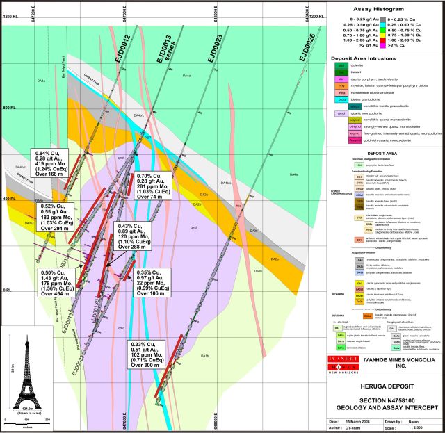
67
Lookout
Hill Project, Mongolia
NI
43-101 Technical Report, June 2009
|
|
Figure
9-5:
|
Generalized
Mo Shell on Heruga Drill Sections (North to
South)
|

68
Entrée
Gold Inc.
Lookout
Hill Project, Mongolia
NI
43-101 Technical Report, June 2009
|
9.3
|
Western
MELs
|
Exploration by
Entrée in 2008 was focused on the Togoot MEL while in previous years exploration
targeted most of the western portion of the Shivee Tolgoi MEL. A
number of mineral occurrences, geophysical and geological targets and
prospective areas have been identified on each. Details of previous
targets can be found in Panteleyev (2004a, 2004b, 2005), Juras (2005),
Cherrywell (2005), Forster (2006), Forster and Crane (2006), Khashgerel et al. (2006), Forster et al. (2008) and Watkins
(2007). The 2008 mineralized zones are described below.
|
|
9.3.1
|
Altan
Khulan Target - Shivee Tolgoi
Licence
|
|
|
The Altan
Khulan target lies in the north eastern corner of the Shivee Tolgoi
licence (Figure 10-2). Host rocks are volcanic, in part
Devonian mafic volcanics believed to be DA1b equivalents (A. Panteleyev,
pers. comm. 2007) and overlain by intermediate volcaniclastic rocks of
probably Carboniferous age. In outcrop, occasional
centimetric-scale quartz veinlets of no great strike extent can be found -
previous prospecting in the area has returned high grade gold assays (4.5
to >8.0g/t Au) from three quartz vein or quartz float grab
samples. In addition, a very weakly anomalous gold-in-soil
response (27.2 - 44.2 ppb Au) from four consecutive 50 m spaced samples
was detected on the northernmost survey line from soil sampling carried
out in 2005. Two diamond drillholes tested this target in 2008
and are discussed in the drilling section below (Section
11).
|
|
|
9.3.2
|
Tom
Bogd Target - Shivee Tolgoi Licence
|
|
|
Tom Bogd
target lies towards the southeast corner of the Shivee Tolgoi licence
(Figure 10-2). MMI soil sampling in 2007 returned anomalous
copper and molybdenum that are coincident with a large IP chargeability
anomaly. One hole was drilled as a test for mineralization at
depth.
|
|
|
9.3.3
|
Coal
Targets - Togoot Licence
|
|
|
Coal has been
exposed by excavator trenching and in core on the Nomkhon Bohr target, and
by drilling on the Coking Flats and Khar Suul targets (Figure
10-2). On all targets, the coal is bituminous to anthracite in
rank, occurring as seams up to several metres thick or as plies of less
than 0.5 metre within carbonaceous mudstones. Rock types
associated with the coal-bearing stratigraphy for each target include
claystones (likely altered airfall tuffs), shales, siltstones, sandstones,
and several types of conglomerate and/or reworked lapilli
tuffs.
|
|
|
Coal exposed
in trenches is oxidized, highly friable, deformed and well banded with ash
partings. Due to oxidization, it is not always possible to
identify individual coal plies within carbonaceous mudstones that
invariably accompany the coal. Trenching also shows that,
despite the complete lack of coal outcrops or coal debris on surface, the
coal can be encountered at depths of less than a metre below
surface.
|
|
|
Coal seams
and plies are readily identified in core. Regardless of
apparent thickness in drill core, the coal is usually dull (du), or banded
dull (badu) - less often, banded bright (babr) and bright (br) coal is
present. Cleating is not well
developed.
|
69
Entrée
Gold Inc.
Lookout
Hill Project, Mongolia
NI
43-101 Technical Report, June 2009
|
|
Although the
Nomkhon Bohr target has been traced in trenches and by drilling for
approximately 1300 metres, individual seams or plies cannot be traced
consistently from hole to hole, on section and along strike because of
problems with incomplete or failed intercepts through the coal-bearing
stratigraphy and lack of downhole geophysical surveys. As well,
the degree of deformation, while complex, is not sufficiently understood
to determine if the coal seams seen in drill core are significantly
thickened or thinned from their pre-deformational
thicknesses. The same holds true for the Coking Flats and Khar
Suul targets.
|
|
|
9.3.4
|
Ring
Dyke Prospect - Togoot Licence
|
|
|
The Ring Dyke
area (also referred to as Snuff Bottle Hill; Figure 10-2) is extensively
underlain by widespread homogeneous hornblende plagioclase porphyry
andesite flows. The andesites are intruded by a sub-volcanic feldspar
porphyry, likely a sub-volcanic plug, and a number of rhyolite domes up to
1 km in size, and numerous small rhyolite
dykes.
|
|
|
Geophysical
surveys (IP and magnetic), prospecting, mapping, diamond and RC drilling
has outlined a zone of sulphide-rich epithermal- or high-level
porphyry-related alteration and mineralization, underlying a variable
thickness of unmineralized Cretaceous gravels. The andesites
and rhyolites are locally intensely clay-altered with kaolinite, dickite,
illite, and alunite. Hematite and limonite, formed from the
oxidation of sulphide minerals, are
common.
|
|
|
Sulphide
mineralology in drill core is dominated by pyrite - rare sphalerite and
chalcopyrite has been observed. The amounts of pyrite
mineralization are sufficient to account for chargeability features that
to date have been the target of deep
drilling.
|
|
|
9.3.5
|
Baruun
Khatnii Guya - Togoot Licence
|
|
|
Khatnii Guya
was discovered by MMI soil sampling in
2007 when significant molybdenum results were
returned (Figure 10-2). The target was outlined and is
underlain by a thick pyroclastic sequence of unaltered ash tuffs and tuff
breccias, intruded by a series of latite sills. No surface
moybdenum mineralization was
observed.
|
70
Entrée
Gold Inc.
Lookout
Hill Project, Mongolia
NI
43-101 Technical Report, June 2009
|
10.0
|
EXPLORATION
|
|
|
Exploration
on the Shivee Tolgoi Project from 2002 through 2007 is summarized in
previous reports (Reid et al., 2003; Reid
et al.,
2004; Cann,
2004; Panteleyev, 2004a; Panteleyev, 2004b; Panteleyev, 2005; Cherrywell,
2005; Juras, 2005; Forster, 2006; and Forster and Crane,
2007). Geophysical methods and diamond drilling have been the
most important exploration tools. Table 10-1 summarizes the
exploration completed on the Project to December 31, 2008. Details of the
2008 program are covered below. Additional detail on drilling
results is given in Section 11.
|
|
|
Table
10-1:
|
Exploration
Summary JV property and Western MELs,
2002-2008
|
|
Year
|
Contractor
|
Company
|
Type
of Exploration Activity
|
Quantity
|
|
2002
|
Entrée
|
Prospecting
and reconnaissance lithogeochemistry
|
75
samples
|
|
|
2002
|
Entrée
|
Trenching
Zone III (576 m)
|
450 chip
samples
|
|
|
2002
|
SJ
Geophysics
|
Entrée
|
IP survey
using pole-dipole array and 50 m electrode spacing. 2 initial
lines.
|
7-8 line
km
|
|
2002-2003
|
Entrée
|
Soil
geochemistry. Samples every 50 m along lines; 5 lines 200 m
apart with another 11 lines 100 m apart.
|
2,140
samples
|
|
|
2003
|
Scott
Geophysics
|
Entrée
|
IP survey
using pole-dipole array and 50 m to 100 m electrode
spacing. Lines spaced 200 m apart.
|
109 line
km
|
|
2003
|
Scott
Geophysics
|
Entrée
|
Ground
magnetics survey. Readings 12.5 m along the
lines. 10 lines spaced 100 m apart and 5 lines 200 m
apart.
|
55.4 line
km
|
|
2003-2004
|
Abitibi
Geophysics
|
Entrée
|
Gravity
survey. 16 lines spaced 200 m apart.
|
114 line
km
|
|
2004
|
XDM
Geological Consultants Inc.
|
Entrée
|
1: 10, 000
scale geological mapping.
|
15 km2
|
|
2004
|
Can Asia
Drilling
|
Entrée
|
Diamond
drilling at the x-Grid (Oortsog) Prospect
|
6 holes - 573
m
|
|
2004-2005
|
Ivanhoe Mines
Ltd.
|
Entrée-Ivanhoe
|
Gradient
array IP survey. 56 lines spaced 100 m; 11 km A-B electrode
spacing initially then 1.2 km, 2 km , 3.1 km, 5 km and 6.6 km electrode
spacing in smaller areas.
|
Approximately
1,562 line km
|
|
2005
|
Ivanhoe Mines
Ltd.
|
Entrée-Ivanhoe
|
Diamond and
RC drilling. Diamond drilling on sections 150 m apart with a nominal 75 m
vertical spacing of pierce points. RC drilling used to define
bedrock geology and as a geochemical exploration tool.
|
55 holes -
43,800 m diamond drill; 57 holes - 3,700 m RC
|
|
2005
|
Entrée
|
Acquisition
and analysis of Aster satellite imagery
|
||
|
2005
|
CanAsia
Drilling and AIDD
|
Entrée
|
Diamond
drilling
|
26 holes
-14,018.31 m
|
|
2005
|
Quantec
Geoscience
|
Entrée
|
IP and
resistivity surveys
|
250 line
km
|
|
2006
|
Ivanhoe Mines
Ltd.
|
Entrée-Ivanhoe
|
Geophysical
survey interpretation
|
|
|
2006
|
Ivanhoe Mines
Ltd.
|
Entrée-Ivanhoe
|
Quarried rock
for use as aggregate in concrete for the shaft foundations and lining at
Oyu Tolgoi; operations discontinued
|
|
|
2006
|
Ivanhoe Mines
Ltd.
|
Entrée-Ivanhoe
|
Diamond and
RC drilling. Includes 12,400 m on the zone east of the proposed
Northern Airport location (Ulaan Khud);
|
40,215 m of
core and
850 m of
RC
|
71
Entrée
Gold Inc.
Lookout
Hill Project, Mongolia
NI
43-101 Technical Report, June 2009
|
Year
|
Contractor
|
Company
|
Type
of Exploration Activity
|
Quantity
|
|
approximately
26,400 m on the Hugo North Extension and 1200 m of geophysical drilling
(collared in Shivee Tolgoi Earn-in Property and drilled back into Hugo
North)
|
||||
|
2006
|
Major
Drilling
|
Entrée
|
Diamond
drilling
|
11 holes -
8,614.1 m
|
|
2006
|
AIDD
|
Entrée
|
RC
drilling
|
18 holes -
3,290.0 m
|
|
2006
|
Entrée
|
Geological
mapping at 1:10,000 scale
|
90 km2
|
|
|
2006
|
Entrée
|
Gradient IP
and resistivity geophysical surveys
|
40 line
km
|
|
|
2006
|
Entrée
|
Reconnaissance
exploration; 16 targets on the Shivee Tolgoi and Togoot
MELs.
|
624 rock chip
samples
|
|
|
2006
|
Dr. Sharon
Carr
|
Entrée
|
Detailed
structural and stratigraphic analysis of Devonian Wedge
prospect
|
|
|
2006
|
Entrée
|
Mobile metal
ion (MMI) soil sampling
|
31
samples
|
|
|
2006
|
PCIGR,
UBC/Jack Satterly Geochron Lab, U of T
|
Entrée
|
Age
dating
|
8
samples
|
|
2006
|
PetraScience
Consultants Inc.
|
Entrée
|
Petrographic
and spectral analysis
|
34 drill core
samples and 15 rock samples
|
|
2007
|
Dr. Sharon
Carr
|
Entrée
|
Detailed
structural and stratigraphic analysis of Khoyor
Mod prospect
|
|
|
2007
|
Major and
AIDD
|
Entrée
|
Diamond
drilling
|
17 holes -
7,712 m
|
|
2007
|
Geocad
|
Entrée
|
Grid
surveying
|
Approx 178
line-km
|
|
2007
|
Geosan
|
Entrée
|
Ground
magnetometer surveying
|
1739
line-km
|
|
2007
|
Geosan
|
Entrée
|
Airborne
magnetic surveying
|
5890
line-km
|
|
2007
|
XDM
Geological Consultants Inc.
|
Entrée
|
1: 20,000 and
10, 000 scale geological mapping.
|
20 km2
|
|
2007
|
Entrée
|
Soil
sampling
|
3859
samples
|
|
|
2007
|
Entrée
|
MMI soil
sampling
|
2065
samples
|
|
|
2007
|
Entrée
|
Excavator
trenching + samples
|
970 m, 485
samples
|
|
|
2007
|
Major
Drilling
|
Ivanhoe
|
Diamond
drilling - Ulaan Khud
|
3 holes 878
m
|
|
2007
|
Major
Drilling
|
Ivanhoe
|
Diamond
drilling - Heruga
|
27 holes -
27,422 m
|
|
2007
|
Major
Drilling
|
Ivanhoe
|
Geotech
drilling - Shivee Tolgoi
|
3 holes -
6,247.2 m
|
|
2008
|
XDM
Geological Consultants Inc.
|
Entrée
|
1: 10,000 and
recon scale geological mapping.
|
North Togoot,
MEL Khatnii Guya
|
|
2008
|
Entrée
|
1:2000 scale
geological mapping
|
North Togoot
licence
|
|
|
2008
|
Entrée
|
Mobile metal
ion (MMI) soil sampling
|
1909
samples
|
|
|
2008
|
Dr. Sharon
Carr
|
Entrée
|
Detailed
structural and stratigraphic analysis of Nomkhon Bohr area
|
|
|
2008
|
Geosan
|
Entrée
|
Ground IP
survey
|
134.4
line-km
|
|
2008
|
Geosan
|
Entrée
|
Ground
magnetometer survey
|
701.90
line-km
|
|
2008
|
Entrée
|
Excavator
trenching + samples
|
313
samples
|
|
|
2008
|
AIDD
|
Entrée
|
Diamond
drilling
|
43 holes -
5934 m
|
|
2008
|
Landdrill
|
Entrée
|
Reverse
Circulation drilling
|
34 holes -
4814 m
|
|
2008
|
Ivanhoe
|
Ground
magnetometer survey - Heruga & Hugo North Ext’n
|
44.2
km
|
|
|
2008
|
Major
Drilling
|
Ivanhoe
|
Diamond
drilling - Heruga
|
14 holes -
24,234 m
|
|
2008
|
Major
Drilling
|
Ivanhoe
|
Diamond
drilling - Ulaan Khud
|
1 hole - 721
m
|
72
Entrée
Gold Inc.
Lookout
Hill Project, Mongolia
NI
43-101 Technical Report, June 2009
|
10.1
|
Shivee
Tolgoi JV Property
|
|
|
10.1.1
|
Introduction
|
|
|
Exploration
on the Oyu Tolgoi Trend was minimal subsequent to completion of the
resource calculation on both Hugo North Extension and the Heruga
deposits. One 721 m diamond hole was drilled on Ulaan Khud,
that lies northeast of Hugo North Extension, and 14 diamond holes were
completed on Heruga as infill and to test the eastern edge of the deposit.
Drilling details are given in Section 11. In addition a
detailed magnetometer survey was completed over Heruga and over the Hugo
North Extension Deposit areas.
|
|
|
10.1.2
|
Hugo
North Extension - Shivee Tolgoi MEL
|
|
|
In late 2008
a 26.6 km2
detailed magnetometer survey was undertaken in the Hugo North
Extension area. Lines were oriented east-west at 25 m spacing
with continuous readings. Two large magnetic features occur in
the survey area. Previous drilling test a minor part of the
anomalies and mineralization was intersected at the southern end 1500 m
below surface and at the northern end in hornfelsed rocks below the thin
Cretaceous clay cover. The orebody does not have a direct
magnetic response but the survey does outline some areas of possible
future interest.
|
|
|
10.1.3
|
Ulaan
Khud - Shivee Tolgoi MEL
|
|
|
One 721 m
diamond drillhole was completed on Ulaan Khud on the Shivee
MEL. Drillhole locations are shown in Section
11. This hole was drilled as an updip test for the extension of
significant mineralization intersected in diamond drillhole EGD127;
however, no significant mineralization was
intersected.
|
|
|
10.1.4
|
Heruga
- Javhlant MEL
|
|
|
In late 2008
a 26.6 km2
detailed magnetometer survey was undertaken in the Heruga area to
get a more detailed view of the geology and structure (Figure
10-1). Lines were oriented east-west at 25 m spacing with
continuous readings. The magnetic survey results combined with
detailed surface mapping established far better understanding of the
geology.
|
|
|
Fourteen
diamond drillholes totaling 24,234 m were completed on the Heruga Deposit
in 2008 to better delineate the deposit. Drilling details are given in
Section 11 below.
|
|
10.2
|
Western
MELs
|
|
|
10.2.1
|
Introduction
|
|
|
The 2008
program on the Shivee Tolgoi MEL involved drill testing of two targets,
Altan Khulan and Tom Bogd (Figure 10-2), identified by exploration in
preceding years. There was no new geophysics or geochemical
surveys carried out in the Shivee MEL in 2008 as part of the target
evaluations.
|
|
|
Exploration
on the Togoot Licence was focused primarily on targets such as Nomkhon
Bohr, Coking Flats, Khar Suul and Toogie East generated through geological
mapping
|
73
Entrée
Gold Inc.
Lookout
Hill Project, Mongolia
NI
43-101 Technical Report, June 2009
|
Figure
10-1:
|
Detailed
magnetic over Heruga Deposit - Javhlant
MEL
|
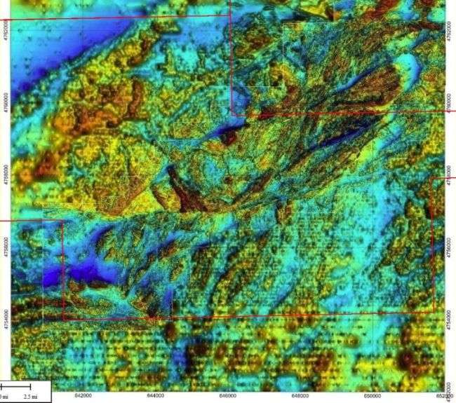
|
|
early in the
2008 season. Follow-up of preceding exploration results on
Ukhaa Tolgod, Baruun Khatnii Guya and Ring Dyke was also
done. Geological mapping at various scales was carried out by
Entrée personnel and by contract personnel Andrejs Panteleyev and Dr.
Sharon Carr (Figure 10-3). This work was complemented by ground
geophysical surveys (magnetometer and IP) by Geosan LLC of Ulaanbaatar,
and MMI soil sampling (Figure 10-4) which was used to screen the targets
for drilling. A number of targets were drilled
tested.
|
|
|
Entrée Gold
contracted Geosan LLC of Ulaanbaatar to undertake geophysical surveys on
the Nomkhon Bohr, Toogie East, Ring Dyke, Ukhaa Tolgod and Coking Flats
Targets. The surveys consisted of Induced Polarization (IP)
plus Resistivity (134.4 line-km of dipole-dipole array surveying), and
Magnetics (701.85 line-km). Work was carried out in three
phases, the first from July 15 to August 28, 2008; the second from
September 19 to October 4, 2008; and the third from October 19 to November
27, 2008. Grids were
|
74
Entrée
Gold Inc.
Lookout
Hill Project, Mongolia
NI
43-101 Technical Report, June 2009
|
|
established
using hand-held GPS units. The results are included in the summary of
individual targets below.
|
|
|
Dipole-dipole
array lines were measured using a set of GDD Instrumentation 2x 3.6kW
(7.2kW) time-domain IP transmitters to input a transmitter pulse of
standard 8000 msec, and an IRIS ELREC Pro time domain IP receiver to
collect the voltages and their decays. The latter recorded
primary voltage (mV), 20 voltage decays, chargeability (msec) and apparent
resistivity (ohm.m) on 6 channels.
|
|
|
Two GSM-19TW
proton magnetometers were employed, one as a base station recording the
diurnal variation of the Earth’s total magnetic intensity (TMI), and the
other mobile unit measuring the TMI along survey lines. The
base station took reading at 5 sec intervals and diurnal correction used a
57200nT base level.
|
75
Entrée
Gold Inc.
Lookout
Hill Project, Mongolia
NI
43-101 Technical Report, June 2009
|
|
Figure
10-2:
|
2008
Targets on Western MELs
|

76
Entrée
Gold Inc.
Lookout
Hill Project, Mongolia
NI
43-101 Technical Report, June 2009
|
|
Figure
10-3:
|
2008
Mapping areas on Western MELs
|
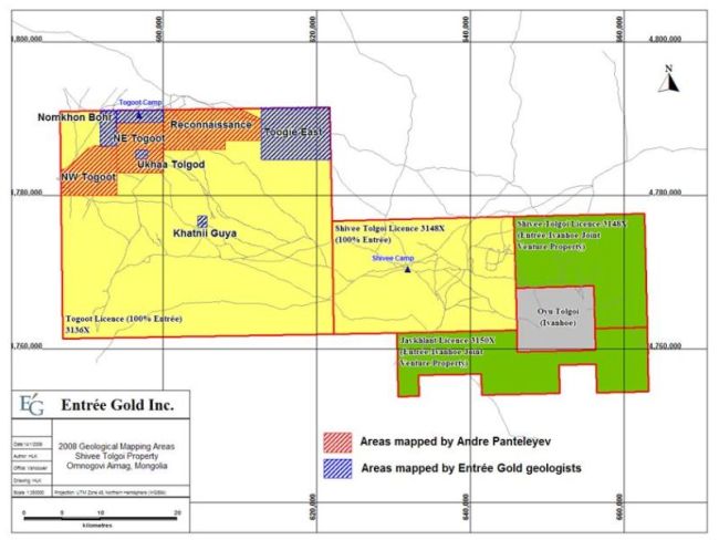
77
Entrée
Gold Inc.
Lookout
Hill Project, Mongolia
NI
43-101 Technical Report, June 2009
|
|
Figure
10-4:
|
2008
MMI sampling areas on Western MELs
|

78
Entrée
Gold Inc.
Lookout
Hill Project, Mongolia
NI
43-101 Technical Report, June 2009
|
|
10.2.2
|
Altan
Khulan Target - Shivee Tolgoi MEL
|
No additional
mapping, sampling or geophysical surveys were done in 2008 in advance of
drilling two holes totalling 363.1 m (see discussion below in Section
11).
|
|
10.2.3
|
Tom
Bogd Target - Shivee Tolgoi MEL
|
Detailed mapping
was done over a portion of the Tom Bogd target (Figure 10-5) prior to drilling
EG-08-090. Previous mapping by Panteleyev (2005) showed that the
target area is underlain by north-striking Carboniferous volcanic rocks lying
east of fine-grained Devonian clastic sedimentary rocks. The latter
are equivalent to unit DA4a at Oyu Tolgoi. Although structural
attitudes are rare in the volcanic rocks, mapping in 2008 showed that a
sedimentary unit within the Carboniferous volcanics dips gently to the
east. This suggests the Devonian basement should be present at depth
underneath the Carboniferous sequence.
|
Figure
10-5:
|
Tom
Bogd Target - 2008 Geology and MMI-Mo
Anomaly
|

79
Entrée
Gold Inc.
Lookout
Hill Project, Mongolia
NI
43-101 Technical Report, June 2009
|
|
The target
was selected to investigate a strong chargeability feature underlying the
Carboniferous stratigraphy. The feature parallels the
north-striking contact with the Devonian sequence. MMI soil
sampling in 2007 outlined high contrast Mo and Cu anomalies that appear to
be directly associated with the chargeability anomaly. The
combined Mo-Cu and chargeability anomalies may be indicating Oyu
Tolgoi-style mineralization in Devonian rocks underlying the Carboniferous
volcanics.
|
|
|
No additional
geophysical or geochemical sampling surveys were carried out on the Tom
Bogd target in 2008. A single diamond core hole was drilled on
the target (see discussion under Section 11) but failed to reach the
planned depth due to drilling
difficulties.
|
|
|
10.2.4
|
Nomkhon
Bohr and Coking Flats Coal Targets - Togoot
MEL
|
|
|
Exploration
at Nomkhon Bohr and Coking Flats consisted of mapping at various scales,
diamond and RC drilling (discussed in detail below in Section 11) and
extensive ground magnetic and IP surveys. Exploration was also conducted
using excavator trenching for prospecting and for geological
mapping.
|
Mapping
|
|
The northwest
corner of the Togoot Licence was mapped at various scales in
2008.Pantelyev (2007, 2008) mapped three areas (North West Togoot, North
Central Togoot, Togoot Reconnaissance in the northwest quarter of the
Togoot Licence, at 1:10,000 and 1:20,000 scales, concentrating mainly on
volcanic and volcaniclastic
|
|
|
Detailed
mapping at 1:2000 by Entrée geologists concentrated along the northern
portion of Panteleyev’s North Central map area, using a Quickbird
satellite image as a map base (Figures 7-6 and 10-3). The main
focus of this mapping was the east-northeast-trending clastic sedimentary
stratigraphy in a basin (the “Nomkhon Bohr basin”) interpreted to be
Permian in age. The mapping also included Carboniferous
basement volcanic stratigraphy of Panteleyev’s map area, which lies south
and west of the basin.
|
|
|
Structural
geology in the Nomhon Bor area was studied by consultant Dr. Sharon Carr
during field work from November 14 to December 14,
2008.
|
|
|
Eleven
excavator trenches were completed on the Nomkon Bohr target to assist in
tracing the coal bearing stratigraphy. No samples were taken from the
trenches as the coal and carbonaceous sediments were generally well
oxidized and not suitable for sampling. The trenches were used for geology
only and are shown in Figure
10-6.
|
80
Entrée
Gold Inc.
Lookout
Hill Project, Mongolia
NI
43-101 Technical Report, June 2009
|
|
Figure
10-6:
|
Nomkhon
Bohr Excavator Trenching
|
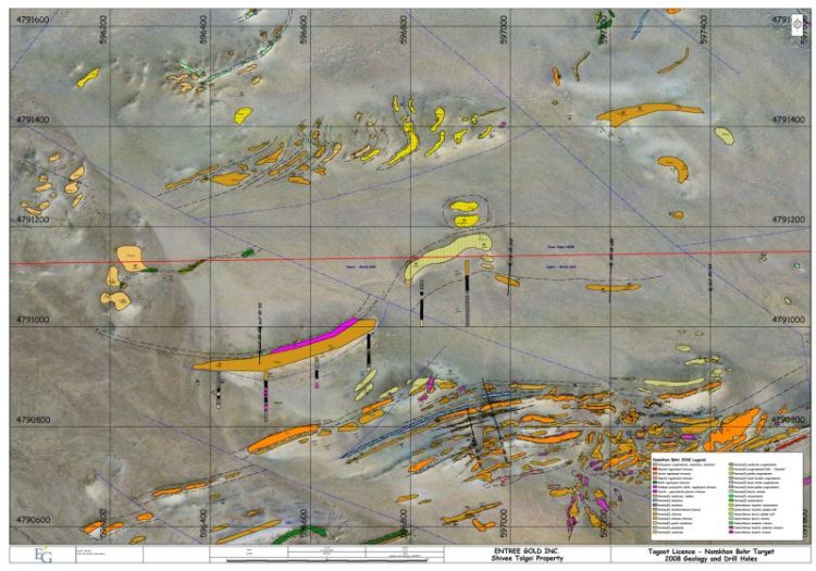
81
Entrée
Gold Inc.
Lookout
Hill Project, Mongolia
NI
43-101 Technical Report, June 2009
Geophysics
|
|
Entrée Gold
contracted Geosan LLC of Ulaanbaatar to undertake geophysical surveys on
the Nomkhon Bohr and Coking Flats Targets (Figures 10-9 and
10-10). The surveys consisted of Induced Polarisation (IP) plus
Resistivity (83.9 line-km of dipole-dipole array surveying), and Magnetics
(558.90 line-km). Grids were established using hand-held GPS
units (Table 10-2).
|
|
Table
10-2:
|
Summary
of 2008 IP Surveys, Togoot
Licence
|
|
Dipole-dipole
IP
|
Magnetics
|
||||||||
|
Survey
area
|
#lines
|
Line
spacing
(m)
|
Comments
|
Duration
|
Total
line
km
|
#lines
|
Line
spacing
(m)
|
Duration
|
Total
line
km
|
|
Nomkhon
Bohr
|
28
|
50m,
100m
|
25m dipole
size, N=6
|
16-30 July
and 19-23 Aug
|
29.5
|
51
|
50
|
23, 24, 28
July and 2, 15 Aug
|
56.55
|
|
Coking
Flats
|
11
|
800
|
25m, 50m
dipole size, N=6
|
24-26 Aug
(11.9km), 21 Oct - 26 Nov (41.5km)
|
53.4
|
136
|
100
|
19 Sept - 5
October
|
502.35
|
|
Ukhaa
Tolgod
|
8
|
50/100
|
50 and 100
dipole size, N=6
|
31 July - 5
Aug
|
10.9
|
15
|
50
|
25,26
July
|
15.0
|
|
Khatnii
Guya
|
11
|
100
|
50m dipole
size, N=6
|
03-14
Aug
|
11.3
|
21
|
50
|
27 and 28
July
|
21.0
|
|
Ring
Dyke
|
11
|
200
|
50m dipole
size, N=6
|
11-17
Aug
|
22.3
|
41
|
50
|
30, 31 July,
1 Aug
|
82.0
|
|
Toogie
East
|
7
|
200
|
50m dipole
size, N=6
|
8-10
Aug
|
7.0
|
25
|
50
|
29
July
|
25.0
|
On Nomkhon Bohr,
resistivity and chargeability anomalies identified appear to be associated with
massive sandstone beds and mafic sills respectively (Figure
10-7). The target stragraphy above the comglomerate is punctuated by
a chargeability high/resistivity low anomaly. The magnetics show the coal
horizon as a mag high at the edge of a sharp trasition from a mag low to the
south (Figure 10-8). At Coking Flats a magnetic anomaly appears to
mark the boundary between the Carboniferous basement and the Cretaceous rocks
(Figures 10-9 and 10-10).
82
Entrée
Gold Inc.
Lookout
Hill Project, Mongolia
NI
43-101 Technical Report, June 2009
|
|
Figure
10-7:
|
Nomkhon
Bohr Resistivity
|

|
|
Figure
10-8:
|
TMI
Nomkhon Bohr Magnetics
|
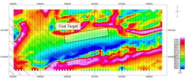
83
Entrée
Gold Inc.
Lookout
Hill Project, Mongolia
NI
43-101 Technical Report, June 2009
|
|
Figure
10-9:
|
TMI
Coking Flats Magnetics
|

|
|
Figure
10-10:
|
Coking
Flats Chargeability
|

84
Entrée
Gold Inc.
Lookout
Hill Project, Mongolia
NI
43-101 Technical Report, June 2009
|
|
10.2.5
|
Ukhaa
Tolgod Target - Togoot MEL
|
|
|
Work by
Entrée keyed on a single grab sample from 2006 that returned 236 ppb
Au. Sampling and trenching exposed Au and Ag mineralization in
two of the east-northeast-trending quartz-veined rhyolitic
dykes.
|
|
|
The Ukhaa
Tolgod area (Figure 10-11) is underlain by a thick sequence of porphyritic
andesitic flows intruded by a series of rhyolitic dykes, probably of
Carboniferous age. In general, the rhyolitic intrusions are not
hydrothermally brecciated or altered beyond minor illite/sericite in small
zones of fractured rock. There is a general absence of sulphide
minerals and iron oxides.
|
|
|
Five hand
trenches (31m) were excavated along the 60 m strike of the silver showing
and chip sampled. Another 325 m were trenched in 8 excavator dug
trenches. Silver, gold and molybdenum results are shown in
Table 10-3.
|
|
Table
10-3:
|
Summary
of Ukhaa Tolgod Trench Assays, Togoot
Licence
|
|
Sample
|
Trench
|
From_m
|
To_m
|
Length_m
|
Ag_ppm
|
Au_ppb
|
Mo_ppm
|
|
314251
|
T314251
|
0.0
|
1.0
|
1.0
|
155
|
621
|
118
|
|
314252
|
T314251
|
1.0
|
2.0
|
1.0
|
90
|
781
|
35
|
|
314253
|
T314251
|
2.0
|
3.0
|
1.0
|
120
|
875
|
85
|
|
314254
|
T314251
|
3.0
|
4.0
|
1.0
|
11
|
44
|
17
|
|
314255
|
T314255
|
0.0
|
1.0
|
1.0
|
57
|
1220
|
20
|
|
314256
|
T314255
|
1.0
|
2.0
|
1.0
|
108
|
1390
|
20
|
|
314257
|
T314255
|
2.0
|
3.0
|
1.0
|
28
|
159
|
8
|
|
314258
|
T314255
|
3.0
|
4.0
|
1.0
|
2
|
23
|
<5
|
|
314259
|
T314255
|
4.0
|
5.0
|
1.0
|
1
|
24
|
<5
|
|
314260
|
T314260
|
0.0
|
1.0
|
1.0
|
21
|
210
|
44
|
|
314261
|
T314260
|
1.0
|
2.0
|
1.0
|
19
|
130
|
11
|
|
314262
|
T314260
|
2.0
|
3.0
|
1.0
|
2
|
12
|
<5
|
|
314263
|
T314260
|
3.0
|
4.0
|
1.0
|
<1
|
2
|
<5
|
|
314264
|
T314260
|
4.0
|
5.0
|
1.0
|
<1
|
3
|
<5
|
|
314265
|
T314260
|
5.0
|
6.0
|
1.0
|
<1
|
11
|
<5
|
|
|
A total of
125 MMI-M samples was collected on a small 400-m x 600-m grid centred on
the mineralized dyke. Good contrast anomalies were outlined for
Au (Figure 10-8) and Ag (Figure 10-9) that coincide with the known
mineralization. Contouring of Ag data suggests that bedrock
mineralization is open to southwest and the east into an area obscured by
thick overburden. Anomalous results for both elements also
indicate a strong response on the southernmost extreme of the grid that
may be indicating the start of another zone of interest. Magnetometer and
IP was completed by Geosan LLC (Table 10-2) over a small area coinciding
with the MMI grid. The mineralized zone coincided with the edge of a mag
low.
|
85
Entrée
Gold Inc.
Lookout
Hill Project, Mongolia
NI
43-101 Technical Report, June 2009
|
|
Figure
10-11:
|
Geology
of the Ukhaa Tolgod Area
|

86
Entrée
Gold Inc.
Lookout
Hill Project, Mongolia
NI
43-101 Technical Report, June 2009
|
|
Figure
10-12:
|
MMI-Au
- Ukhaa Tolgod Grid, Togoot Licence
|

87
Entrée
Gold Inc.
Lookout
Hill Project, Mongolia
NI
43-101 Technical Report, June 2009
|
Figure
10-13:
|
MMI-Ag
- Ukhaa Tolgod Grid, Togoot Licence
|
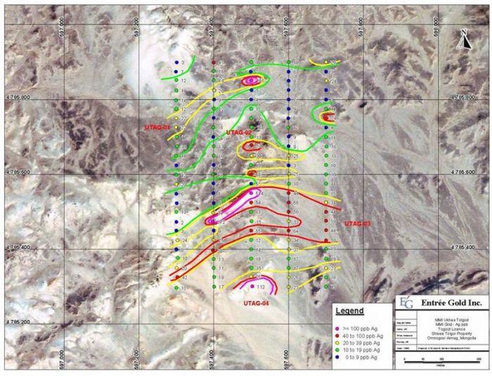
88
Entrée
Gold Inc.
Lookout
Hill Project, Mongolia
NI
43-101 Technical Report, June 2009
|
|
10.2.6
|
Baruun
Khatnii Guya Target - Togoot MEL
|
|
|
MMI soil
sampling in 2007 returned a significant Mo target, lying north of a series
of east-west trending rhyolite domes. The MMI sampling from 2007 details
are included in the March 2008 technical report (Vann et al., 2008) under the
name of Khatnii Guya West. The domes display clear flow-banding
in places and are surrounded by a more dacitic flow unit and a dacitic
tuff breccia-ignimbrite unit in the “outer rim”. Intense
argillic alteration within the tuff units (mostly kaolinite-illite, rare
hypogene alunite is present) mark a clear colour anomaly. Northeast- and
minor northwest-trending quartz veins and faults (defined by strongly
oxidised fault breccias) cut the dome sequence (Figure
10-10). Conglomerates are found northeast of the quartz
vein/fault zone.
|
|
|
Magnetometer
and IP surveys by Geosan LLC (Table 10-2) were done over the MMI sampling
grid. The total field magnetics map is bisected by a
northeast-trending magnetic high/magnetic low couple, coincident with the
zone of quartz veins and strongly oxidised fault breccias. This
zone marks the location of a major fault, dividing the conglomerates
northeast of the fault from the rhyolite dome sequence to the
southwest. The strongest MMI-Mo responses overlie the
conglomeratic sequence.
|
|
|
The MMI-Mo
target itself sits over an area underlain by a thick pyroclastic sequence
of unaltered ash tuffs and tuff breccias, intruded by a series of latite
sills. No surface moybdenum mineralization was
observed.
|
|
|
Additional
MMI sampling (85 samples) was undertaken by Entrée personnel in 2008 to
expand the existing coverage. This sampling did not extend the
known anomaly along strike, and the target was not selected for
drilling.
|
|
|
10.2.7
|
Ring
Dyke Target - Togoot MEL
|
The target was
mapped previously by Panteleyev (2007) and was not remapped in
2008. It comprises a zone of silicified and limonitic outcrops that
form a circular pattern with an approximate 1 km diameter. The zone
is cut by clay- and silica-altered mineralized rhyolitic dykes and overlain by a
rhyolite dome complex consisting of flows, flow breccias and
dykes. No outcropping zones of base or precious metals mineralization
were identified by exploration prior to 2008. Nonetheless, MMI soil
sampling was undertaken to look for indications of blind
mineralization.
|
|
MMI soil
sampling was done by Entrée personnel on a 2 km x 3.2 km grid; 75 samples
were collected in total. No significant base or precious metals
anomalies were returned from this
work.
|
|
|
Magnetometer
and IP surveys by Geosan LLC (Table 10-2) were done over the MMI sampling
grid.
|
|
|
Given the
lack of significant MMI soil geochemical anomalies, the target was not
selected for drilling and no further work is
recommended.
|
89
Entrée
Gold Inc.
Lookout
Hill Project, Mongolia
NI
43-101 Technical Report, June 2009
|
|
Figure
10-14:
|
Geology
of the Baruun Khatnii Guya Area
|
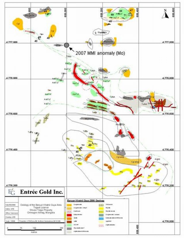
90
Entrée
Gold Inc.
Lookout
Hill Project, Mongolia
NI
43-101 Technical Report, June 2009
|
|
10.2.8
|
Toogie
East Target - Togoot MEL
|
|
|
The majority
of this area is underlain by two volcanic sequences: a southern dacitic
pyroclastic sequence (locally with welded textures) and a northern
andesitic to locally rhyolitic pyroclastic sequence with minor
intercalated clastic sedimentary rocks (Figure 10-11). Pyrite
clasts were observed in lapilli tuffs of the southern pyroclastic
sequence. Both sequences are probably Carboniferous in age,
although the sedimentary rocks in the northern sequence have some
similarities to clastic sedimentary rocks in the Nomkhon Bohr area, which
are assigned to the Permian.
|
|
|
MMI soil
sampling was done by Entrée personnel on a 700 m x 800 m grid; 451 samples
were collected for MMI-M analyses. No significant base or
precious metals anomalies were returned from this
work.
|
|
|
Magnetometer
and IP surveys by Geosan LLC (Table 10-2) were done over the MMI sampling
grid.
|
|
|
Given the
lack of significant MMI soil geochemical anomalies, the target was not
selected for drilling, and no further work is
recommended.
|
91
Entrée
Gold Inc.
Lookout
Hill Project, Mongolia
NI
43-101 Technical Report, June 2009
|
|
Figure
10-15:
|
Toogie
East Geology
|

92
|
11.0
|
DRILLING
|
|
|
11.1
|
General
|
|
|
Approximately
172, 000 m of drilling has been completed on the Lookout Hill property
from 2004 to December 31, 2008 (Table 11-1) by Ivanhoe and by Entree.
Drilling has been predominantly core and on the JV Property (eastern
Shivee Tolgoi and Javhlant MELs) by project operator Ivanhoe Mines. The
majority of the diamond drilling has been exploration related and includes
45 holes totalling 43,283 m on the Hugo North Extension deposit and 40
holes totalling 53,823 m on the Heruga
deposit.
|
|
|
All drilling
completed on the JV Property has been by operated by Ivanhoe, except for
six early-stage core holes drilled by Entrée at the X-Grid (Oortsog)
Prospect, prior to the Earn-in Agreement being signed. Diamond
drilling has been the source of all geological and grade data in support
of the Mineral Resource estimates completed on the Hugo North Extension
Deposit. A small percentage of the drilling (two holes
totalling 736 m) is from combined RC/core drilling, which has RC drilling
at the top of the hole in barren rock and core drilling once
mineralization is encountered.
|
|
|
Since 2002,
Entrée has completed 109 diamond drillholes totalling 40,579 m and 52 RC
holes totalling 8,104 m. 2008 drilling was mainly focused on coal
exploration in the northwest corner of the Togoot
licence.
|
|
|
11.2
|
Shivee
Tolgoi JV Property - Shivee Tolgoi
MEL
|
|
11.2.1
|
Introduction
|
|
|
Ivanhoe has
completed three years drilling on the JV property with most drilling
focused on the Ulaan Khud (Airport North) and Hugo North Extension zones
on the Shivee Tolgoi MEL and on the Heruga deposit on the Javhlant
MEL. In addition, Ivanhoe has completed a significant amount of
condemnation and water exploration drilling (RC and core) in the vicinity
of the Hugo North Extension (66 holes totalling 4,311 m). These
holes have been to assist in the determination of suitable sites for
proposed tailings and other infrastructure purposes and to find water
sources for the proposed mining operation at the adjacent Oyu Tolgoi
Project. The condemnation and water holes are not considered in
detail in this report. Ivanhoe has also drilled early-stage
exploration holes at the Ulaan Khud prospect (core and
RC).
|
|
|
Drillholes on
the JV Property are identified in the Property database with either the
prefix “EG”, for holes located on the Shivee Tolgoi MEL, or by “EJ”, for
holes located on the Javhlant MEL. The prefix is followed by
“D” for diamond drillholes, “RC” for reverse circulation holes, and “RCD”
for RC holes with diamond tails. Geotechnical, water and
condemnation drillholes do not receive a special prefix, and are
identified by the drilling method.
|
|
|
Exploration
diamond drilling is contracted to Major Pontil Pty Ltd. (Major), based out
of Australia, who are using a variety of rigs, some with depth
capabilities close to 2,000 m. Rigs which have recently been,
or are currently on site, include UDR 1000, 1500
and
|
93
Entrée
Gold Inc.
Lookout
Hill Project, Mongolia
NI
43-101 Technical Report, June 2009
|
|
Table
11-1:
|
Lookout
Hill Project - Drilling Summary
|
|
Deposit/Prospect
|
DDH
Holes
|
Length
of DDH (m)
|
RC
Holes
|
Length
RC Holes (m)
|
RC/DDH
Holes(4)
|
Length
RC/DDH (m)
|
All
Holes(1)
|
Total
Length (m)
(1)
|
|
100%
Entrée MELs
|
|
|
|
|
|
|
|
|
|
Zone
I
|
17
|
8174.95
|
6
|
914
|
-
|
-
|
23
|
9088.95
|
|
Zone
II
|
2
|
418.50
|
-
|
-
|
-
|
-
|
2
|
418.50
|
|
Zone
III
|
10
|
4293.05
|
5
|
761
|
-
|
-
|
15
|
5054.05
|
|
Ring
Dyke
|
4
|
2415.54
|
7
|
1615
|
-
|
-
|
11
|
4030.54
|
|
Bayan-Ovoo
|
9
|
5337.40
|
-
|
-
|
-
|
-
|
9
|
5337.40
|
|
West Grid
Mo
|
7
|
4067.78
|
-
|
-
|
-
|
-
|
7
|
4067.78
|
|
West Grid
IP
|
3
|
3315.60
|
-
|
-
|
-
|
-
|
3
|
3315.60
|
|
West Grid -
Dev Wedge
|
2
|
1605.50
|
-
|
-
|
-
|
-
|
2
|
1605.50
|
|
BZMo
|
2
|
244.00
|
-
|
-
|
-
|
-
|
2
|
244.00
|
|
Khoyor
Mod
|
5
|
2831.10
|
-
|
-
|
-
|
-
|
5
|
2831.10
|
|
Manakhad
|
2
|
277.30
|
-
|
-
|
-
|
-
|
2
|
277.30
|
|
Altan
Khulan
|
3
|
767.00
|
-
|
-
|
-
|
-
|
3
|
767.00
|
|
Tom
Bogd
|
1
|
592.20
|
-
|
-
|
-
|
-
|
1
|
592.20
|
|
South
Boundary
|
2
|
1260.20
|
-
|
-
|
-
|
-
|
2
|
1260.20
|
|
Coking
Flats
|
6
|
826.50
|
27
|
3974
|
-
|
-
|
33
|
4800.50
|
|
Khar
Suul
|
11
|
1817.80
|
4
|
549
|
-
|
-
|
15
|
2366.80
|
|
Nomkhon
Bohr
|
23
|
2334.94
|
3
|
291
|
-
|
-
|
26
|
2625.94
|
|
Total
|
109
|
40,579.36
|
52
|
8,104.00
|
0
|
0
|
161
|
48,683.36
|
|
JV
Property
|
|
|
|
|
|
|
|
|
|
Hugo North
Extension (2)
|
45
|
42547.00
|
-
|
-
|
2
|
736
|
82
|
43,283.0
|
|
Condemnation/Water
|
-
|
-
|
66
|
4311
|
-
|
-
|
66
|
4311.00
|
|
Ulaan
Khud
|
36
|
17,401.0
|
28
|
2500
|
-
|
-
|
28
|
19,901.0
|
|
X-Grid
(Oortsog)(3)
|
6
|
572.75
|
-
|
-
|
-
|
-
|
6
|
572.75
|
|
Heruga
|
40
|
53,822.9
|
-
|
-
|
-
|
-
|
29
|
53,822.9
|
|
Castle
Rock
|
2
|
2097.60
|
-
|
-
|
-
|
-
|
2
|
2097.60
|
|
SW Mag
Anomaly
|
1
|
409.00
|
-
|
-
|
-
|
-
|
1
|
409.00
|
|
Total
JV
|
118
|
116,129.3
|
94
|
6,811.00
|
2
|
736
|
214
|
123,676.3
|
|
Grand
Total
|
227
|
156,708.7
|
146
|
14,915.00
|
2
|
736
|
375
|
172,359.6
|
Notes:
(1) Includes all
holes drilled to December 31, 2008. (2) A portion of these holes were collared
in the Shivee Tolgoi Earn-in Property and drilled into the Oyu Tolgoi
Property (3) These holes were drilled by Entrée prior to the Earn-in
Agreement being signed. (4) RC holes with diamond drillhole
tails.
94
Entrée
Gold Inc.
Lookout
Hill Project, Mongolia
NI
43-101 Technical Report, June 2009
5000 and Major 50
drills. The vast majority of core at the Property has either been
PQ-size (85 mm nominal core diameter) or HQ-size (63.5 mm nominal core
diameter), with a small percentage using NQ-size (47.6 mm nominal core
diameter). Most holes are now collared with PQ core and are reduced
to HQ at depths of around 500 m prior to entering the mineralized
zone. A few holes have continued to depths of about 1,300 m using PQ
diameter equipment.
|
|
Core drilling
and database procedures have been extensively described in reports by
Cinits and Parker (2007) and Peters et al.
(2006). Additional details on core handling are provided in
Sections 12 and 13.
|
|
|
All drilling
completed on the JV Property has been by operated by Ivanhoe, except for
six early-stage core holes drilled by Entrée at the X-Grid (Oortsog)
Prospect, prior to the Earn-in Agreement being signed. Diamond
drilling has been the source of all geological and grade data in support
of the Mineral Resource estimates completed on the Hugo North Extension
Deposit. A small percentage of the drilling (two holes
totalling 736 m) is from combined RC/core drilling, which has RC drilling
at the top of the hole in barren rock and core drilling once
mineralization is encountered.
|
|
|
The following
descriptions are based on work completed at both the Hugo North (on the
adjacent Oyu Tolgoi Project) and Entrée’s Hugo North Extension
Deposits. Since both are one continuous zone of mineralization,
the supporting database was evaluated as a whole and one block model was
constructed to estimate the Mineral Resources. Later, the
resources were cut at the Property boundary for reporting purposes; thus
discussion of drilling protocols that were in place during the exploration
for all of the Hugo North and Hugo North Extension Deposits is
warranted.
|
|
|
11.2.2
|
Hugo
North Extension Exploration Diamond
Drilling
|
No new drilling was
carried out on the Hugo North Extension Deposit in 2008. Details of
previous drilling can be found in the March 2008 NI 43-101 report (Vann et al., 2008)
|
|
11.2.3
|
Hugo
North Extension Drill Results
|
No new drill
results were received on the Hugo North Extension Deposit in
2008. Details of previous drilling can be found in the March 2008 NI
43-101 report (Vann et
al., 2008)
|
|
11.2.4
|
Ulaan
Khud (Airport North) Diamond
Drilling
|
Approximately
16,680 m (35 drillholes) of exploration drilling was completed on this trend
(mainly in 2006 and early 2007) and lead to the discovery of a low grade zone of
mineralization averaging less than 0.3% copper (Figure 11-1). The
narrow, steeply dipping zone is 30 to 50 m in width, has a north-south strike
length of approximately 900 m, and a vertical extent of up to 600
m. Narrow, patchy high grade copper and gold intervals provided
encouragement that a higher grade zone might be encountered however after
extensive drilling only the low grade zone was delineated.
95
Entrée
Gold Inc.
Lookout
Hill Project, Mongolia
NI
43-101 Technical Report, June 2009
|
|
Figure
11-1:
|
Ulaan
Khud Drillhole Locations
|

One diamond
drillhole (EGD142) totalling 731 m was drilled on this target in 2008 (Table
11-2). The hole was drilled on the same section as EGD127, EGD130 and EGD132.
EGD127 intersected very significant Cu-Au-Mo mineralization including 2m of
2.92ppm Au, 7.28% Cu and 5330ppm Mo. EGD142 was designed to test the up-dip
extension of mineralization but failed to intersect significant
mineralization.
96
Entrée
Gold Inc.
Lookout
Hill Project, Mongolia
NI
43-101 Technical Report, June 2009
|
|
Table
11-2:
|
Ulaan
Khud 2008 Drilling Summary
|
|
Zone
|
Hole
Number
|
UTM
Coordinates
|
Elevation
(masl)
|
Azimuth
(°)
|
Dip
(°)
|
Length
(m)
|
|
|
Easting
|
Northing
|
||||||
|
Ulaan
Khud
|
EGD0042
|
655200
|
4775400
|
-
|
270
|
60
|
721.0
|
|
Total
|
1
hole
|
721.0
|
|||||
|
|
11.2.5
|
Geotechnical
Drilling
|
No
new geotechnical drilling was completed in 2008. Details of previous
drilling can be found in the March 2008 NI 43-101 report (Vann et al., 2008)
|
|
11.3
|
Shivee
Tolgoi JV Property - Javhlant MEL
|
|
|
11.3.1
|
Introduction
|
|
|
To the end of
2008, over 54,000 metres in 43 holes m had been completed on Javhlant
(Table 11-3 and Figure 11-2). All of the drilling has been by
core methods and was completed by Ivanhoe Mines as part of the JV
Agreement. The majority of the drilling has been focused on
delineating the Heruga deposit; 40 holes were drilled for a total of
53,931.4m. Elsewhere on Javhlant, the two holes were drilled in
the Castle Rock IP anomaly and a single hole was drilled in the SW
Magnetic anomaly.
|
|
|
Drillholes on
the JV Property are identified in the Property database with “EJ”, for
holes located on the Javhlant MEL. The prefix is followed by
“D” for diamond drillholes, “RC” for reverse circulation holes, and “RCD”
for RC holes with diamond tails. Geotechnical, water and
condemnation drillholes do not receive a special prefix, and are
identified by the drilling method.
|
|
|
Exploration
diamond drilling is contracted to Major Pontil Pty Ltd. (Major), based out
of Australia, who are using a variety of rigs, some with depth
capabilities close to 2,000 m. Rigs which have recently been,
or are currently on site, include UDR 1000, 1500 and 5000 and Major 50
units. The vast majority of core diameters at the Property have
either been PQ-size (85 mm nominal core diameter) or HQ-size (63.5 mm
nominal core diameter), with a small percentage using NQ-size (47.6 mm
nominal core diameter). Most holes are now collared with PQ
core and are reduced to HQ at depths of around 500 m prior to entering the
mineralized zone. A few holes have continued to depths of about
1,300 m using PQ diameter.
|
|
|
Core drilling
and database procedures have been extensively described in reports by Vann
et al. (2008),
Cinits and Parker (2007) and Peters et al.
(2006).
|
97
Entrée
Gold Inc.
Lookout
Hill Project, Mongolia
NI
43-101 Technical Report, June 2009
|
|
Table
11-3:
|
Javhlant
MEL Drilling Summary to March 03,
2009
|
|
Hole
Number
|
UTM
Coordinates
|
Elevation
(masl)
|
Azimuth
(°)
|
Dip
(°)
|
Final
Depth
(m)
|
Length
(m)
|
|
|
Easting
|
Northing
|
||||||
|
Heruga
|
|||||||
|
EJD0001
|
648016.8
|
4759300
|
1162.73
|
270.2
|
69.92
|
1137.8
|
1137.8
|
|
EJD0001A
|
648016.8
|
4759300
|
1162.73
|
270.2
|
69.92
|
1724.2
|
586.4
|
|
EJD0003
|
647695.8
|
4759300
|
1163.48
|
270.39
|
69.43
|
1302.8
|
1302.8
|
|
EJD0004
|
647369.8
|
4757897
|
1168.36
|
270.28
|
69.68
|
922.7
|
922.7
|
|
EJD0005
|
647398.6
|
4759298
|
1164.19
|
268.35
|
69.76
|
1087.1
|
1087.1
|
|
EJD0006
|
647265.2
|
4757891
|
1165.51
|
267.95
|
60.96
|
870.9
|
870.9
|
|
EJD0007
|
647996.7
|
4758998
|
1162.13
|
273.51
|
69.76
|
1325
|
1325
|
|
EJD0008
|
648299.4
|
4759297
|
1164.63
|
270.1
|
68.94
|
1018.9
|
1018.9
|
|
EJD0008A
|
648299.4
|
4759297
|
1164.63
|
270.1
|
68.94
|
1817.4
|
1817.4
|
|
EJD0009
|
647669.2
|
4757899
|
1167.5
|
269.24
|
70.52
|
1163.2
|
1163.2
|
|
EJD0010
|
647648.5
|
4758398
|
1166.04
|
271.63
|
70.04
|
1258.2
|
1258.2
|
|
EJD0011
|
647750
|
4758696
|
1161.45
|
272.51
|
78.48
|
1729.1
|
1729.1
|
|
EJD0012
|
647649
|
4758099
|
1166.52
|
270.11
|
70
|
1130.6
|
1130.6
|
|
EJD0013
|
647851.6
|
4758100
|
1167.13
|
271.07
|
70.22
|
1353.1
|
1353.1
|
|
EJD0013A
|
647851.6
|
4758100
|
1167.13
|
271.07
|
70.22
|
1123.3
|
622.3
|
|
EJD0013B
|
647851.6
|
4758100
|
1167.13
|
271.07
|
70.22
|
1404
|
802
|
|
EJD0014
|
647848
|
4758399
|
1166.39
|
271.79
|
70.53
|
1629.6
|
1629.6
|
|
EJD0015
|
647947.4
|
4758700
|
1161.28
|
270.38
|
85.37
|
1417
|
1417
|
|
EJD0015A
|
647947.4
|
4758700
|
1161.28
|
270.38
|
85.37
|
980.4
|
980.4
|
|
EJD0017
|
647869.3
|
4757899
|
1166.45
|
272.03
|
70.64
|
577.7
|
577.7
|
|
EJD0017A
|
647869.3
|
4757899
|
1166.45
|
272.03
|
70.64
|
1558.3
|
1049.3
|
|
EJD0019
|
647882.7
|
4757733
|
1164.77
|
261.05
|
72.9
|
598.2
|
598.2
|
|
EJD0019A
|
647882.7
|
4757733
|
1164.77
|
261.05
|
72.9
|
1557.6
|
991.6
|
|
EJD0020
|
648300.1
|
4758999
|
1163.09
|
272.21
|
70.3
|
1482.2
|
1482.2
|
|
EJD0020A
|
648300.1
|
4758999
|
1163.09
|
272.21
|
70.3
|
1471.5
|
1471.5
|
|
EJD0021
|
648047.4
|
4758401
|
1164.38
|
271.63
|
69.92
|
1744.5
|
1744.5
|
|
EJD0022
|
648068.9
|
4757889
|
1165.8
|
269.11
|
70.74
|
1899.9
|
1899.9
|
|
EJD0023
|
648050
|
4758098
|
1164.61
|
271.45
|
69.99
|
1660.3
|
1660.3
|
|
EJD0024
|
648252.5
|
4758399
|
1163.1
|
272.95
|
70.73
|
1973.4
|
1973.4
|
|
EJD0025
|
648000.2
|
4759498
|
1163.92
|
267.35
|
70.16
|
1449.7
|
1449.7
|
|
EJD0026
|
648452.3
|
4758100
|
1159.75
|
270.54
|
69.27
|
1807.3
|
1807.3
|
|
EJD0027
i
|
647937.6
|
4759144
|
1163.72
|
270.9
|
75.67
|
1788.3
|
1788.3
|
|
EJD0028
i
|
648200
|
4759500
|
1163
|
270.12
|
69.85
|
1764.1
|
1764.1
|
|
EJD0029
i
|
648251.6
|
4758398
|
1163.1
|
272.95
|
81.28
|
1723.5
|
1723.5
|
|
EJD0029A
i
|
648251.6
|
4758398
|
1163.1
|
272.95
|
81.28
|
1775.9
|
1141.9
|
|
EJD0030
i
|
647484
|
4757700
|
1162
|
271.55
|
70.2
|
1794.6
|
1794.6
|
|
EJD0031
i
|
648362
|
4759499
|
1166
|
274.45
|
70.09
|
1801
|
1801
|
|
EJD0032
i
|
647233
|
4757700
|
1160
|
268.94
|
70.27
|
1632.6
|
1632.6
|
|
EJD0033
i
|
648229
|
4758094
|
1154
|
269.79
|
67
|
1520.3
|
1520.3
|
|
EJD0034
i
|
648565
|
4759500
|
1153
|
269.83
|
65
|
1905
|
1905
|
|
40
holes
|
Total
|
53931.4
|
|||||
|
Castle
Rock
|
|||||||
|
EJD0016
|
650600
|
4757600
|
1160
|
270
|
60
|
1151.5
|
1151.5
|
|
EJD0018
|
649000.8
|
4756607
|
1158.86
|
89.71
|
61.2
|
946.1
|
946.1
|
|
2
holes
|
2097.6
|
||||||
|
SW
Mag
|
|||||||
|
EJD0002
|
637502
|
4759503
|
1214
|
90
|
60
|
1151.5
|
1151.5
|
|
1
hole
|
1151.5
|
||||||
98
Entrée
Gold Inc.
Lookout
Hill Project, Mongolia
NI
43-101 Technical Report, June 2009
|
|
11.3.2
|
Exploration
Diamond Drilling at Heruga
|
|
|
Exploration
diamond drilling at Heruga has been completed by diamond coring methods,
with drilling using PQ, HQ or NQ core sizes. Drilling has not
used triple tube to date. Most holes are collared in PQ and
reduced to HQ and in some instance NQ at depth. To the 22
February, 2008, approximately 38% of core was PQ, 55% HQ and 7%
NQ.
|
|
|
The general
treatment and handling of core for Heruga is as described in Section
12. QG observed all steps in core handling with the exception
of marking orientation lines and cutting core (although core saws were
examined). QG make the following observations and
recommendations:
|
|
|
•
|
Ivanhoe
maintains consistency of observations from hole to hole and between
different loggers by conducting regular internal checks. QG also
recommends Ivanhoe ensure that actual observations are logged with respect
to lithology rather than attempting to match a genetic
model.
|
|
|
•
|
The manual
logging system in place is potentially more error-prone than digital
capture systems and recommends that such systems be investigated by
Ivanhoe.
|
|
|
•
|
Samples
should respect lithological, alteration or mineralization
boundaries. Although this will have a negligible implication
for future resource estimates, it is considered good practice and will
improve the estimation quality. Duplicate core samples should not be taken
at a contact.
|
|
|
•
|
The core
storage at Oyu Tolgoi represents a possible risk to the project. Given the
long possible project life, the ability to locate core for the purposes of
either re-logging or re-sampling is
emphasized.
|
|
|
All
exploration diamond drillholes at Heruga are drilled approximately grid
west, generally at about 70 degree inclinations. However the
holes tend to deviate systematically towards north at
depth. The general orientation of drilling is considered to be
appropriate, but it is likely some drilling at high angles to the
‘cross-section’ (i.e. to the north or south) will be undertaken in future
campaigns to resolve a number of geological uncertainties (for example the
disposition of the mineralized quartz
monzodiorite).
|
|
|
QG
independently checked collar survey in the database versus surveyors’
records and conclude that the data used is
sound.
|
99
Entrée
Gold Inc.
Lookout
Hill Project, Mongolia
NI
43-101 Technical Report, June 2009
|
|
Figure
11-2:
|
Drillhole
Location on IP, Heruga Deposit
|

Downhole
Surveys at Heruga
|
|
Where
possible, the core was oriented, initially using BallMark© but more
recently using the electronic ACE© core orientation system (a fully
electronic system based on accelerometers). QG consider that
both of these devices are appropriate means of orienting core, and note
that the frequency of core orientation on this project is
appropriate.
|
Recoveries
and RQD at Heruga
|
|
Core recovery
at Heruga is generally very good. Average recovery at Heruga to
date is 97%-100%, with the relatively rare poorly recovered intervals
invariably correlated to shearing and
faulting.
|
100
Entrée Gold Inc.
Lookout
Hill Project, Mongolia
NI
43-101 Technical Report, June 2009
|
|
QG examined
all the core in hole EJD-009 as well as significant runs (450-500 m) from
holes EJD-013 and EJD-021 and confirmed that, in general, recovery was
good and core condition (with the exception of faults) also very
good.
|
|
|
Ivanhoe
informed QG that RQD is not being recorded for Heruga core, nor has
geotechnical logging been taking place, although this was reportedly
standard practice at Oyu Tolgoi and Hugo Dummett. If the
project progresses, geotechnical logging should be reinstituted as a
routine step, because the quality of data from half core is
lower.
|
Bulk
Densities at Heruga
|
|
QG spent time
on site with Dale A. Sketchley (Ivanhoe Manager QA/QC Advanced Projects)
to confirm that the procedures described in this report are applicable to
the core sample preparation for the Heruga
deposit.
|
|
|
QG performed
an inspection of the equipment and samples being subjected to specific
gravity determination on site (accompanied by Dale A.
Sketchley). This visit did not constitute an
audit. Ivanhoe retained an independent geologist/geochemist,
Barry Smee, to conduct audits of preparation and analytical facilities
(Smee, 2002a, 2002b, 2003a, 2003b, 2004a, 2004b, 2004c, 2004d, 2005, 2006,
2008).
|
|
|
QG make the
following comments about bulk density estimation at
Heruga:
|
|
|
•
|
The size of
samples is small - typically samples are half core and less than 10cm in
length. As a result the precision of individual determinations
will be relatively poor. QG recommend that Ivanhoe make
determinations on the largest available pieces of core (this may require
modified equipment, but is
straightforward);
|
|
|
•
|
Currently
measurements are taken on one small piece of core every 10 m
drilled. QG argue that the density data is very important and
that measurements should be more frequent, ideally on all available intact
core;
|
|
|
•
|
Ideally
measurements should be made on whole core;
and
|
|
|
•
|
The outside
repeating of core bulk density determinations is important and should be
performed at an offshore laboratory. A recent program to run
such checks at the Genalysis UB facility resulted in very poor data due to
insufficient training of the laboratory staff (samples were broken into
small pieces before measurements were
taken).
|
|
|
In summary,
improvements need to be made to the process to increase precision of the
data, but the data are likely to be acceptable in aggregate (i.e. when
averaged) for an Inferred resource.
|
|
|
11.3.3
|
Heruga
Drill Results
|
Drill locations in
the Heruga Deposit are shown in Figure 11-2 and two representative drill
sections are shown in Figures 11-3 and 11-4. All significant drill
results to the end of July, 2008 from Heruga are summarized below in Table
11.4.
101
Entrée
Gold Inc.
Lookout
Hill Project, Mongolia
NI
43-101 Technical Report, June 2009
|
|
Figure
11-3:
|
Geology
and Mineralization Section N4758100, Looking
North
|

|
|
Note:
Figure from Ivanhoe Mines
|
102
Entrée Gold Inc.
Lookout
Hill Project, Mongolia
NI
43-101 Technical Report, June 2009
|
|
Figure
11-4:
|
Geology
and Mineralization Section N4757900, Looking
North
|

Note:
Figure from Ivanhoe Mines
103
Entrée
Gold Inc.
Lookout
Hill Project, Mongolia
NI
43-101 Technical Report, June 2009
|
|
Table
11-4:
|
Selected
Mineralized Intervals from the Heruga Deposit, 2008
Drilling
|
|
Hole
ID
From-to
metres (m)
|
Interval
m
|
Cu
%
|
Au
g/t
|
Mo
ppm
|
CuEq*
%
|
|
EJD0027
|
|||||
|
852.0 -
1776.0
|
924.0
|
0.49
|
0.59
|
131
|
0.93
|
|
Incl. 1252.0
- 1390.0
|
138.0
|
0.67
|
1.17
|
81
|
1.46
|
|
EJD0028
|
|||||
|
1064.0 -
1556.0
|
492.0
|
0.53
|
0.55
|
167
|
0.97
|
|
EJD0029
|
|||||
|
1472.0 -
1698.0
|
226.0
|
0.27
|
0.52
|
27
|
0.62
|
|
Incl. 1558.0
- 1586.0
|
28.0
|
0.64
|
0.88
|
72
|
1.24
|
|
EJD0029A
|
|||||
|
1016.0 -
1450.0
|
434.0
|
0.37
|
0.40
|
121
|
0.69
|
|
Incl. 1294.0
- 1306.0
|
12.0
|
1.93
|
1.62
|
907
|
3.44
|
|
1582.0 -
1770.0
|
188.0
|
0.40
|
0.47
|
47
|
0.72
|
|
EJD0030
|
|||||
|
1042.0 -
1174.0
|
132.0
|
0.35
|
0.34
|
119
|
0.64
|
|
1222.0 -
1682.0
|
460.0
|
0.35
|
0.30
|
115
|
0.61
|
|
EJD0031
|
|||||
|
1118.0 -
1560.0
|
442.0
|
0.53
|
0.31
|
151
|
0.80
|
|
Incl. 1226.0
- 1292.0
|
66.0
|
0.83
|
0.21
|
336
|
1.14
|
|
Incl. 1456.0
- 1538.0
|
82.0
|
0.83
|
0.75
|
183
|
1.40
|
|
EJD0032
|
|||||
|
1298.0 -
1462.0
|
164.0
|
0.36
|
0.27
|
142
|
0.60
|
|
EJD0033
|
|||||
|
1004.0 -
1214.0
|
210.0
|
0.37
|
0.32
|
108
|
0.64
|
|
EJD0034
|
|||||
|
1142.0 -
1384.0
|
242.0
|
0.49
|
0.19
|
189
|
0.71
|
104
Entrée
Gold Inc.
Lookout
Hill Project, Mongolia
NI
43-101 Technical Report, June 2009
|
|
11.4
|
Western
MELs (100% Entrée)
|
|
|
11.4.1
|
Introduction
|
|
|
Total
drilling from 2004 to the end 2008 on the Western MELs includes 115
diamond drillholes totaling 40,611 m and 52 reverse-circulation drillholes
totaling 8104 m.
|
|
|
The focus of
the 2008 program was on the Togoot MEL where an extensive diamond and
reverse circulation drill campaign was carried out. A small
program of three holes were drilled to test two targets on the Shivee
Tolgoi MEL. On Togoot, the main goal was to outline coal zones
in the northernmost portion of the claim on the Nomkhon Bohr, Coking Flats
and Khar Suul areas. Details of drill exploration activities
from 2004-2007 can be found in Cherrywell, 2005; Panteleyev, 2005; Cinits
and Parker, 2007; Vann et al.,
2008.
|
|
|
A total of
4,814 m of reverse-circulation (“RC”) drilling in 34 holes and 4,979 m of
diamond drilling in 40 holes was completed on the Togoot Licence in 2008
(Table 11-1, Figure 16). RC and diamond drilling operations,
conducted under contract with Landdrill International LLC of Ulaanbaatar,
commenced on September 28, 2008 and completed on November 7, 2008. A
second diamond drill was contracted to A.I.D.D., Ulaanbaatar and commenced
early October 2008. Drill collars were located using a handheld
GPS.
|
|
|
A total of
955 metres of core drilling in three holes was completed on the western
portion of the Shivee Tolgoi Licence in 2008 (Table 11-5, Figure
11-5). Two targets were tested - Altan Khulan (gold) and Tom
Bogd (copper - molybdenum). Drilling operations, conducted
under contract with AIDD, commenced on October 9, 2008 and completed on
November 3, 2008.
|
|
|
Core drilling
and database procedures have been extensively described in reports by
Cinits and Parker (2007) and Peters et al.
(2006). Additional details on core handling are provided
in Sections 12 and 13.
|
|
|
All diamond
core from the drilling campaign is stored in a fenced location at the camp
site. The new core is in very good condition; all having been
cut with a diamond saw, and stored in wooden core boxes dead-staked on the
ground. The adjacent core-logging room is large and well-lit,
with electric lighting and a concrete floor. There is a
facility with two diamond core saws in a separate building adjacent to the
core storage area.
|
|
|
As part of
the 2008 QA/QC program (see Section 13.4) 256 quarter-core field duplicate
samples were submitted. Currently no bulk density samples are
collected.
|
|
|
The logging
procedures by Entrée are as follows from the arrival at the core
shed:
|
|
|
•
|
Quick
review.
|
|
|
•
|
Geotechnical
logging, using pre-established codes and logging forms, including: length
of core run, recovered/drilled ratio, and maximum
length.
|
|
|
•
|
Core logging
and marking of geological structures, mineralization, and layout of
appropriate sampling intervals.
|
|
|
•
|
Sampling: the
geologist marks a cutting line, and marks the 2.0 m sample
intervals.
|
105
Entrée Gold Inc.
Lookout
Hill Project, Mongolia
NI
43-101 Technical Report, June 2009
|
|
•
|
Core
photography.
|
|
|
•
|
Core cutting:
with a diamond saw, following the line marked by the
geologist.
|
|
|
•
|
Sample
bagging: always half-core samples collected from the same side of the
core, properly identified with inner tags and outside marked
numbers. Sample bags are immediately sealed and stored in a
fenced facility at the camp site. Samples are delivered under
lock and key by Entrée personnel directly to the SGS Mongolia laboratory
in Ulaanbaatar on an approximate weekly
basis.
|
|
|
•
|
Geological
logging, and logging forms, in accordance with the company protocol
includes: header information, geotechnical data (described above),
lithology description and coding, structural description and angle to core
axis, mineralization and alteration and assay
interval.
|
|
|
•
|
Assay data
entry: the assay results are imported to a proprietary database maintained
by Century Database Systems in Sudbury, Ontario,
Canada.
|
|
|
•
|
Drill log
data entry: coded data are introduced into the Century Database Logger
files by a technician (single data
entry).
|
|
|
•
|
At the
completion of the logging process, the boxes are returned to the core
racks.
|
|
|
11.4.2
|
Exploration
Diamond Drilling - Shivee Licence
|
|
|
A total of
955 metres of core drilling in three holes was completed on the western
portion of the Shivee Tolgoi Licence in 2008 (Table 11-5, Figure
11-5). Two targets were tested - Altan Khulan (gold) and Tom
Bogd (copper - molybdenum). Drilling operations, conducted
under contract with AIDD, commenced on October 9, 2008 and completed on
November 3, 2008.
|
|
|
AIDD supplied
a UDR-600 track-mounted drill rig. All core was HQ in
diameter. Recovery was using standard wireline equipment and
core barrels. Downhole surveys to determine hole deviation were
taken with a Reflex EZ shot digital
camera.
|
|
|
Table
11-5:
|
2008
Core Hole Drilling Summary - Shivee Tolgoi
Licence
|
|
HOLE
|
E_WGS84Z48
|
N_WGS84Z48
|
ELEVATION
|
TARGET
|
AZ
|
DIP
|
DEPTH
|
|
EG-08-086
|
642025
|
4774602
|
1220
|
Altan
Khulan
|
270
|
-60
|
271.70
|
|
EG-08-088
|
642051
|
4774704
|
1220
|
Altan
Khulan
|
270
|
-60
|
91.40
|
|
EG-08-090
|
642325
|
4765751
|
1206
|
Tom Bogd
MMI
|
270
|
-80
|
592.20
|
|
TOTAL
METRES
|
955.30
|
||||||
|
|
Core
recoveries obtained by the drilling contractor have been very good, except
in localized areas of faulting or
fracturing.
|
106
Entrée Gold Inc.
Lookout
Hill Project, Mongolia
NI
43-101 Technical Report, June 2009
|
|
Figure
11-5:
|
2008
Drill collar locations on Shivee Tolgoi
Licence
|

107
Entrée
Gold Inc.
Lookout
Hill Project, Mongolia
NI
43-101 Technical Report, June 2009
|
|
11.4.3
|
Drill
Results - Shivee Tolgoi Licence
|
Altan
Khulan Target
|
|
Two holes,
EG-08-086 and EG-08-088 were drilled to follow up on a gold intercept
(4.14 grams/tonne Au over 4.0 m) in EG-07-065, associated with an MMI-Au
anomaly outlined in 2007. The mineralization in EG-07-065
comprised very weakly altered intermediate volcanics, believed to be
Carboniferous in age. Fifty-five samples were taken for Au and
Ag analyses. Although both holes in 2008 intersected
similar-looking altered volcanics, there were no significant results -
best Au was 267ppb over 1.5 m.
|
Tom
Bogd Target
|
|
Due to
drilling problems, EG-08-090 was abandoned at 592.2 metres while still in
Carboniferous volcanics. No significant sulphide mineralization
was observed in the core, and the source(s) of the chargeability and
molybdenum anomalies remains unexplained. One hundred and
thirteen samples exhibiting weak alteration (chloritization,
sericitization, silicification) in Carboniferous volcaniclastic and
pyroclastic rocks were collected and submitted for Au and Ag
analyses. There were no significant analytical
results.
|
|
|
11.4.4
|
Exploration
Drilling - Togoot Licence
|
Core
Drilling
|
|
The core
drilling program for coal tested three targets in the northwest corner of
the Togoot Licence: Nomkhon Bohr, Coking Flats, and Khar
Suul. A total of 4,979 metres of core drilling in 40 holes was
completed on the Togoot Licence in 2008 (Table 11-6, Figure
11-6).
|
|
|
Drilling
operations, conducted under contracts with Landdrill International LLC and
AIDD LLC, both of Ulaanbaatar, commenced on July 31, 2008 and completed on
December 10, 2008. Landdrill provided an LEM3000 truck-mounted drill
rig. Drilling began with HQ equipment, using split-tube core
barrels to maximize recovery. This was later changed to PQ
equipment, using triple-tube recovery. In addition, PCD open
hole drilling was used in a couple of holes to drill through thick
Cretaceous cover rocks. AIDD provided the UDR-600 rig, again using HQ
equipment but switching to split tube recovery for the coal drilling
work.
|
|
|
A total of
950 coal core samples were sent to SGS Mongolia LLC in Ulaanbaatar for
preparation and determination of lump relative density. Of these, 837 were
then sent to SGS-CSTC Standards Technical Services Co., Ltd in Tianjin,
China for specific gravity, proximate analysis, total Sulphur %, and
calorific value. In addition, free swell index was determined on 400 of
the 837 samples. As of the date of this report, not all analytical results
had been received from Tianjin - analytical results are only available up
to EG-08-085. Thirty-seven coal samples were also sent to Loring
Laboratories Ltd., Calgary, Canada for check
analyses.
|
|
|
Following
standard coal industry practice, core from coal holes was not split and
the entire core sample was sent for analysis after logging and
photography.
|
|
|
Holes are
inclined at a range of azimuths and dips (refer to Table 11-6) depending
upon the orientation of the drill target. Entrée conducts
downhole directional surveys on all core holes using a Reflex EZ shot
digital camera. Readings are corrected by 3.5°W to account for
magnetic
|
108
Entrée Gold Inc.
Lookout
Hill Project, Mongolia
NI
43-101 Technical Report, June 2009
|
|
Table
11-6:
|
2008
Core Hole Drilling Summary - Togoot
Licence
|
|
HOLE
|
SIZE
|
E_WGS84Z48
|
N_WGS84Z48
|
ELEV
|
TARGET
|
AZ
|
DIP
|
DEPTH
|
STATUS
|
|
EG-08-066
|
HQ
|
596980
|
4790777
|
1337
|
Nomkhon
Bohr
|
345
|
-45
|
174.80
|
Completed
|
|
EG-08-067
|
HQ
|
596930
|
4790765
|
1338
|
Nomkhon
Bohr
|
345
|
-45
|
117.30
|
Completed
|
|
EG-08-068
|
HQ
|
596999
|
4791125
|
1328
|
Nomkhon
Bohr
|
180
|
-65
|
151.70
|
Completed
|
|
EG-08-069
|
HQ
|
597201
|
4791125
|
1330
|
Nomkhon
Bohr
|
180
|
-65
|
36.00
|
Abandoned
|
|
EG-08-070
|
HQ
|
597201
|
4791125
|
1330
|
Nomkhon
Bohr
|
180
|
-62
|
169.50
|
Completed
|
|
EG-08-071
|
HQ
|
597400
|
4791075
|
1336
|
Nomkhon
Bohr
|
180
|
-60
|
46.00
|
Abandoned
|
|
EG-08-072
|
HQ
|
597400
|
4791075
|
1336
|
Nomkhon
Bohr
|
180
|
-42
|
66.00
|
Abandoned
|
|
EG-08-073
|
HQ
|
596499
|
4790950
|
1327
|
Nomkhon
Bohr
|
180
|
-45
|
35.80
|
Abandoned
|
|
EG-08-074
|
HQ
|
596500
|
4790998
|
1325
|
Nomkhon
Bohr
|
180
|
-70
|
55.49
|
Abandoned
|
|
EG-08-075
|
PQ
|
596500
|
4791026
|
1324
|
Nomkhon
Bohr
|
180
|
-70
|
69.10
|
Abandoned
|
|
EG-08-076
|
PQ
|
596200
|
4790950
|
1322
|
Nomkhon
Bohr
|
180
|
-70
|
80.25
|
Abandoned
|
|
EG
08-077
|
PQ
|
596775
|
4791100
|
1333
|
Nomkhon
Bohr
|
180
|
-65
|
127.60
|
Completed
|
|
EG
08-078
|
PQ
|
596900
|
4790950
|
1331
|
Nomkhon
Bohr
|
360
|
-45
|
90.50
|
Completed
|
|
EG
08-079
|
PQ
|
597000
|
4790925
|
1330
|
Nomkhon
Bohr
|
360
|
-45
|
108.30
|
Completed
|
|
EG
08-080
|
PQ/HQ
|
597100
|
4791125
|
1334
|
Nomkhon
Bohr
|
180
|
-65
|
148.60
|
Completed
|
|
EG
08-081
|
PQ/HQ
|
597300
|
4791075
|
1338
|
Nomkhon
Bohr
|
180
|
-65
|
67.70
|
Abandoned
|
|
EG
08-082
|
PQ
|
597500
|
4791070
|
1340
|
Nomkhon
Bohr
|
180
|
-65
|
114.00
|
Abandoned
|
|
EG
08-083
|
PQ
|
597300
|
4791120
|
1337
|
Nomkhon
Bohr
|
180
|
-65
|
134.80
|
Abandoned
|
|
EG
08-084
|
PQ
|
597100
|
4791155
|
1333
|
Nomkhon
Bohr
|
180
|
-80
|
151.70
|
Completed
|
|
EG
08-085
|
PQ
|
596900
|
4791120
|
1330
|
Nomkhon
Bohr
|
180
|
-65
|
117.00
|
Abandoned
|
|
EG
08-087
|
PQ
|
596900
|
4791120
|
1330
|
Nomkhon
Bohr
|
360
|
-90
|
211.90
|
Completed
|
|
EG-08-089
|
PQ
|
593907
|
4788797
|
1305
|
Coking
Flats
|
135
|
-45
|
150.40
|
Completed
|
|
EG-08-091
|
PQ
|
593942
|
4788762
|
1305
|
Coking
Flats
|
135
|
-45
|
125.00
|
Completed
|
|
EG-08-092
|
PQ
|
593872
|
4788832
|
1307
|
Coking
Flats
|
135
|
-50
|
149.00
|
Completed
|
|
EG-08-093
|
HQ
|
591273
|
4789876
|
1273
|
Khar
Suul
|
360
|
-90
|
285.85
|
Completed
|
|
EG-08-094
|
PQ
|
593766
|
4788651
|
1302
|
Coking
Flats
|
135
|
-65
|
147.10
|
Completed
|
|
EG-08-095
|
PCD/PQ
|
593837
|
4788580
|
1304
|
Coking
Flats
|
135
|
-65
|
86.70
|
Completed
|
|
EG-08-096
|
HQ
|
591131
|
4789734
|
1275
|
Khar
Suul
|
360
|
-90
|
220.25
|
Completed
|
|
EG-08-097
|
PCD/PQ
|
593683
|
4788549
|
1305
|
Coking
Flats
|
135
|
-65
|
168.30
|
Completed
|
|
EG-08-098
|
HQ
|
590921
|
4789669
|
1270
|
Khar
Suul
|
360
|
-90
|
92.15
|
Completed
|
|
EG-08-099
|
HQ
|
591059
|
4789522
|
1274
|
Khar
Suul
|
135
|
-75
|
138.65
|
Completed
|
|
EG-08-100
|
HQ
|
591284
|
4789429
|
1275
|
Khar
Suul
|
315
|
-52
|
250.20
|
Completed
|
|
EG-08-101
|
PQ
|
592952
|
4790035
|
1288
|
Khar
Suul
|
360
|
-90
|
72.30
|
Completed
|
|
EG-08-102
|
HQ
|
588390
|
4788940
|
1247
|
Khar
Suul
|
360
|
-90
|
142.75
|
Completed
|
|
EG-08-103
|
HQ
|
591105
|
4789325
|
1271
|
Khar
Suul
|
315
|
-52
|
175.70
|
Completed
|
|
EG-08-104
|
HQ
|
591070
|
4789360
|
1271
|
Khar
Suul
|
315
|
-52
|
167.40
|
Completed
|
|
EG-08-105
|
HQ
|
590405
|
4789190
|
1264
|
Khar
Suul
|
315
|
-52
|
146.15
|
Abandoned
|
|
EG-08-106
|
HQ
|
596300
|
4790960
|
1325
|
Nomkhon
Bohr
|
180
|
-70
|
33.10
|
Abandoned
|
|
EG-08-107
|
HQ
|
593022
|
4789965
|
1290
|
Khar
Suul
|
360
|
-90
|
126.40
|
Abandoned
|
|
EG-08-108
|
HQ
|
596200
|
4791020
|
1322
|
Nomkhon
Bohr
|
225
|
-60
|
27.80
|
Abandoned
|
|
TOTAL
METRES
|
4979.24
|
||||||||
109
Entrée
Gold Inc.
Lookout
Hill Project, Mongolia
NI
43-101 Technical Report, June 2009
|
|
Figure
11-6:
|
2008
Diamond drillhole collar locations on Togoot
Licence
|

110
Entrée
Gold Inc.
Lookout
Hill Project, Mongolia
NI
43-101 Technical Report, June 2009
|
|
declination. Entree
personnel review the downhole survey files to check for abrupt azimuth or
dip changes that may suggest the presence of false deviations from
magnetic interferences or inappropriately collected
readings.
|
|
|
Drill
sections are plotted using MapInfo Discover® software, and show
generalized lithology alteration and
mineralization.
|
RC
Drilling
|
|
A total of
4,814 metres of reverse-circulation (RC) drilling in 34 holes was
completed by Entrée on the Togoot Licence in 2008 (Table 11-7, Figure
11-7). Drilling operations, conducted under contract with Landdrill
Drilling, commenced on September 28, 2008 and were completed on November
7, 2008.
|
|
|
Table
11-7:
|
Reverse
Circulation Drilling - Togoot
Licence
|
|
HOLE
|
E_WGS84Z48
|
N_WGS84Z48
|
ELEV
|
TARGET
|
AZ
|
DIP
|
DEPTH
|
|
EG-RC-08-019
|
596500
|
4791026
|
1359
|
Nomkhon
Bohr
|
180
|
-70
|
141
|
|
EG-RC-08-020
|
596200
|
4790950
|
1359
|
Nomkhon
Bohr
|
180
|
-70
|
51
|
|
EG-RC-08-021
|
596400
|
4790950
|
1359
|
Nomkhon
Bohr
|
180
|
-60
|
99
|
|
EG-RC-08-022
|
593824
|
4789590
|
1308
|
Coking
Flats
|
135
|
-60
|
140
|
|
EG-RC-08-023
|
593894
|
4789519
|
1310
|
Coking
Flats
|
000
|
-90
|
144
|
|
EG-RC-08-024
|
593965
|
4789448
|
1312
|
Coking
Flats
|
000
|
-90
|
140
|
|
EG-RC-08-025
|
594036
|
4789377
|
1312
|
Coking
Flats
|
000
|
-90
|
140
|
|
EG-RC-08-026
|
594389
|
4789024
|
1312
|
Coking
Flats
|
315
|
-60
|
140
|
|
EG-RC-08-027
|
594248
|
4789165
|
1313
|
Coking
Flats
|
135
|
-60
|
133
|
|
EG-RC-08-028
|
594136
|
4788708
|
1306
|
Coking
Flats
|
135
|
-60
|
150
|
|
EG-RC-08-029
|
594065
|
4788779
|
1305
|
Coking
Flats
|
135
|
-60
|
150
|
|
EG-RC-08-030
|
593994
|
4788850
|
1308
|
Coking
Flats
|
135
|
-60
|
150
|
|
EG-RC-08-031
|
593924
|
4788920
|
1310
|
Coking
Flats
|
135
|
-60
|
150
|
|
EG-RC-08-032
|
593853
|
4788991
|
1308
|
Coking
Flats
|
135
|
-60
|
150
|
|
EG-RC-08-033
|
593782
|
4789062
|
1312
|
Coking
Flats
|
000
|
-90
|
150
|
|
EG-RC-08-034
|
593570
|
4789274
|
1304
|
Coking
Flats
|
000
|
-90
|
150
|
|
EG-RC-08-035
|
594136
|
4788427
|
1306
|
Coking
Flats
|
135
|
-60
|
150
|
|
EG-RC-08-036
|
594066
|
4788497
|
1304
|
Coking
Flats
|
135
|
-60
|
150
|
|
EG-RC-08-037
|
593995
|
4788568
|
1303
|
Coking
Flats
|
135
|
-60
|
147
|
|
EG-RC-08-038
|
593924
|
4788639
|
1303
|
Coking
Flats
|
135
|
-60
|
150
|
|
EG-RC-08-039
|
593853
|
4788710
|
1301
|
Coking
Flats
|
135
|
-60
|
150
|
|
EG-RC-08-040
|
593783
|
4788780
|
1302
|
Coking
Flats
|
135
|
-60
|
150
|
|
EG-RC-08-041
|
591608
|
4788409
|
1281
|
Coking
Flats
|
135
|
-60
|
140
|
|
EG-RC-08-042
|
591537
|
4788480
|
1279
|
Coking
Flats
|
135
|
-60
|
150
|
|
EG-RC-08-043
|
591467
|
4788550
|
1277
|
Coking
Flats
|
135
|
-60
|
150
|
|
EG-RC-08-044
|
591396
|
4788621
|
1276
|
Coking
Flats
|
135
|
-60
|
150
|
|
EG-RC-08-045
|
591343
|
4789664
|
1273
|
Khar
Suul
|
135
|
-60
|
147
|
|
EG-RC-08-046
|
591276
|
4789733
|
1272
|
Khar
Suul
|
135
|
-60
|
150
|
|
EG-RC-08-047
|
591202
|
4789805
|
1272
|
Khar
Suul
|
135
|
-60
|
102
|
|
EG-RC-08-048
|
591195
|
4789820
|
1271
|
Khar
Suul
|
360
|
-90
|
150
|
|
EG-RC-08-049
|
589970
|
4787080
|
1262
|
Coking
Flats
|
135
|
-60
|
150
|
|
EG-RC-08-050
|
590129
|
4786925
|
1265
|
Coking
Flats
|
000
|
-90
|
150
|
|
EG-RC-08-051
|
589699
|
4785368
|
1260
|
Coking
Flats
|
000
|
-90
|
150
|
|
EG-RC-08-052
|
589062
|
4784874
|
1263
|
Coking
Flats
|
000
|
-90
|
150
|
|
TOTAL
METRES
|
4814
|
||||||
111
Entrée Gold Inc.
Lookout
Hill Project, Mongolia
NI
43-101 Technical Report, June 2009
|
|
Figure
11-7:
|
2008
RC Drillhole Collar Locations on Togoot
Licence
|

112
Entrée
Gold Inc.
Lookout
Hill Project, Mongolia
NI
43-101 Technical Report, June 2009
|
|
The RC holes
were planned to a maximum depth of approximately 150 metres, limited by
the length of drill rods available and by the practical chip-return limit
of the compressor.Following normal industry practice, reverse circulation
holes were not sampled for coal (due to significant loss of or addition of
moisture and loss of volatile matter) - only logged
geologically.
|
|
|
Down hole
geophysical logging was done on most RC holes through a contract with
Monkarotaj geophysical logging services of Ulaanbaatar, Mongolia. Holes
were logged for density (both long normal and short normal density), gamma
ray, self potential, resistivity, and i open-hole calipers. Results were
used for seam definition and for stratigraphic
correlation.
|
|
|
No downhole
directional surveys were undertaken for RC
holes.
|
|
|
11.4.5
|
Downhole
Geophysical Surveys
|
|
|
Downhole
geophysics was done on most core and RC holes. The surveys
aided in lithological logging and stratigraphic
correlation.
|
|
|
Monkarotaj
LLC was the contractor for downhole geophysical surveying. Four
types of tools or sondes (manufactured by Auslog Pty. Ltd.) were used:
gamma ray, density, SPPR, and caliper, both inside-the-tube and open
hole.
|
|
|
Gamma ray
tools detect natural gamma radiation emanating from the subsurface
rocks. The logs provide a clear indication of variations in
lithology and also help to define bed thickness. Shaley bands
can be identified because clay content results in a high gamma
count. The gamma ray log is also used for identification of
coal, as coal typically exhibits a low count
rate.
|
|
|
The unusually
low density of coal means that it may be identified readily by the density
tool. The actual value of the density can be empirically
calibrated to provide an indication of the ash content. Thin
partings and seam splits may be easily
discerned.
|
|
|
Spontaneous
Potential (SP) log measures small, naturally occurring spontaneous
potential generated by electrochemical differences between differing rock
types, water and drilling fluids.
|
|
|
PR (point
resistance) measurements are used to ascertain depths and thicknesses of
strata. These measurements will often clearly define the strata
boundaries. In coal work, electrical resistivity logs indicate
the presence of coal (high resistance) and can be a good tool for picking
parting contacts. Anomalous readings of the resistivity can also indicate
that the seam has been coked by an igneous intrusion, or has been affected
by oxidation.
|
|
|
The caliper
sonde is an electromechanical unit that, by use of a spring-loaded arm,
gives a measurement of borehole diameter. This shows the change
between competent units and softer more readily eroded units. The caliper
log is usually run in conjunction with the density log and is used to map
caved zones; caving can give rise to spurious readings from the density
tool.
|
|
|
Downhole
surveying was used for 14 of the RC drillholes and 16 of the core
holes.
|
113
Entrée Gold Inc.
Lookout
Hill Project, Mongolia
NI
43-101 Technical Report, June 2009
|
|
11.4.6
|
Drill
Results - Togoot MEL
|
|
|
The core
drilling tested three coal targets in the northwest corner of the Togoot
Licence: Nomkhon Bohr, Coking Flats, and Khar Suul (Figure
11-7).
|
|
|
Stratigraphy
hosting the Nomkhon Bohr target comprises fine-grained clastic sedimentary
rocks (fine conglomerates, sandstones, siltstones) with a volcaniclastic
component (lapilli tuffs, fine ash deposits, reworked pyroclastic
deposits) and minor limestone beds. No coal crops out on surface but it
has been traced by drilling and trenching over a strike length of 1,300
metres. Coal was intersected in discovery hole EG-08-068. In total, 23
holes totalling 2,335 metres were drilled on this target. Of these, 12
holes were abandoned due to drilling problems, and three (EG-08-066,
EG-08-067, EG-08-079) were off target. A section through Nomkhon Bohr is
shown in Figure 11-8.
|
|
|
Analyses to
date indicate the Nomkhon Bohr coal is predominantly low- to
medium-volatile bituminous in rank with some analyses indicating
anthracite coal rank as determined by applying PARR formula. The coal is
high in ash with variable sulphur. Coal-bearing horizons in
drillholes can be up to 57 metres in apparent thickness; within these,
multiple high-ash coal seams are usually present, ranging in apparent
thickness from 0.2 metres to 4.35 metres. True thicknesses are
uncertain due to possible repetition of the host stratigraphy. The coal
can be considered to have potential for heating or power generation, but
not for metallurgical purposes.
|
|
|
The Coking
Flats and Khar Suul coal discoveries were made by drilling. Six holes
totalling 826.5 metres were drilled on the Coking Flats target; 11 holes
totalling 1,817.8 metres were drilled on the Khar Suul target. The coal
stratigraphy of each is overlain by Cretaceous conglomerates and
sandstones. At Coking Flats, the thickness of Cretaceous conglomerates can
be in excess of 130 metres. Coal intercepts are much narrower when
compared to Nomkhon Bohr. Other than relative density, no analytical
results have been received from any of the holes on these
targets.
|
|
|
The RC
drilling had two objectives:
|
|
|
•
|
to drill
through the western extension of the Nomkhon Bohr target which was not
properly tested by core drilling;
and
|
|
|
•
|
to prospect
the Coking Flats area for coal stratigraphy underneath Cretaceous
sedimentary rocks.
|
|
|
The RC
drilling had mixed results for both objectives. Only one of the
holes on the Nomkhon Bohr target (EG-RC-08-019) was successful in getting
to ultimate depth. EG-RC-08-020 and EG-RC-08-021 were abandoned
due to collapsing ground. The drilling on the Coking Flats led
to the discovery of the Coking Flats and Khar Suul coal
targets. However, 13 of the 31 RC holes in the Coking Flats
area bottomed in Cretaceous sedimentary rocks or in Carboniferous basement
rocks without intersecting Permian coal-bearing stratigraphy. A
representative drill section through Coking Flats is shown in Figure 11-9.
RC drill results are outlined in Table
11-8.
|
114
Entrée Gold Inc.
Lookout
Hill Project, Mongolia
NI
43-101 Technical Report, June 2009
|
|
Figure
11-8:
|
Representative
Core and RC Section Through Nomkhon
Bohr
|

115
Entrée
Gold Inc.
Lookout
Hill Project, Mongolia
NI
43-101 Technical Report, June 2009
|
|
Figure
11-9:
|
RC
Drill Section - Coking Flats
|

116
Entrée
Gold Inc.
Lookout
Hill Project, Mongolia
NI
43-101 Technical Report, June 2009
|
|
Table
11-8:
|
Reverse-Circulation
Drilling Results - Togoot Licence
|
|
HOLE
|
DEPTH
|
TARGET
|
COMMENTS
|
|
EG-RC-08-019
|
141
|
Nomkhon
Bohr
|
Re-entered
EG-08-075.
|
|
EG-RC-08-020
|
51
|
Nomkhon
Bohr
|
Re-entered
EG-08-076, but failed to penetrate further. Only air-core used,
no RC. Lost at 51 metres
|
|
EG-RC-08-021
|
99
|
Nomkhon
Bohr
|
Lost in
liquefied mud. Hole collapse
|
|
EG-RC-08-022
|
140
|
Coking
Flats
|
Cretaceous to
EOH
|
|
EG-RC-08-023
|
144
|
Coking
Flats
|
Cretaceous to
EOH
|
|
EG-RC-08-024
|
140
|
Coking
Flats
|
Cretaceous to
EOH
|
|
EG-RC-08-025
|
140
|
Coking
Flats
|
Cretaceous to
EOH
|
|
EG-RC-08-026
|
140
|
Coking
Flats
|
Cretaceous to
46m, Carboniferous volcanics to EOH
|
|
EG-RC-08-027
|
133
|
Coking
Flats
|
Cretaceous to
40m, Permian to 75m, Carboniferous volcanics to EOH
|
|
EG-RC-08-028
|
150
|
Coking
Flats
|
Cretaceous to
26m, clay to 31m, Permian to 69m, Carboniferous volcanics to
EOH
|
|
EG-RC-08-029
|
150
|
Coking
Flats
|
OVB/clay to
19m, Permian carbonaceous mudstones to 62m, Carboniferous volcanics to
EOH
|
|
EG-RC-08-030
|
150
|
Coking
Flats
|
Cretaceous to
56m, Permian carbonaceous mudstones to 103m, Carboniferous volcanics to
EOH
|
|
EG-RC-08-031
|
150
|
Coking
Flats
|
Cretaceous to
148m, Carboniferous volcanics to EOH
|
|
EG-RC-08-032
|
150
|
Coking
Flats
|
Cretaceous to
EOH
|
|
EG-RC-08-033
|
150
|
Coking
Flats
|
Cretaceous to
EOH
|
|
EG-RC-08-034
|
150
|
Coking
Flats
|
Cretaceous to
38m, Permian to EOH
|
|
EG-RC-08-035
|
150
|
Coking
Flats
|
Cretaceous to
EOH
|
|
EG-RC-08-036
|
150
|
Coking
Flats
|
Cretaceous to
72m, Permian to EOH
|
|
EG-RC-08-037
|
147
|
Coking
Flats
|
Clay to 44m,
Permian to EOH
|
|
EG-RC-08-038
|
150
|
Coking
Flats
|
Cretaceous to
75m, Permian + carbonaceous mudstones to EOH
|
|
EG-RC-08-039
|
150
|
Coking
Flats
|
Cretaceous to
91m, Permian + carbonaceous mudstones to EOH
|
|
EG-RC-08-040
|
150
|
Coking
Flats
|
Cretaceous to
EOH
|
|
EG-RC-08-041
|
140
|
Coking
Flats
|
Cretaceous to
60m; Carboniferous volcanics to EOH
|
|
EG-RC-08-042
|
150
|
Coking
Flats
|
Cretaceous to
26m; Permian sediments to EOH
|
|
EG-RC-08-043
|
150
|
Coking
Flats
|
Cretaceous to
20m; Permian sediments to EOH
|
|
EG-RC-08-044
|
150
|
Coking
Flats
|
Cretaceous to
23m; Permian sediments to EOH
|
|
EG-RC-08-045
|
147
|
Khar
Suul
|
Cretaceous to
14m; intrusives to 61m; Permian sediments to EOH
|
|
EG-RC-08-046
|
150
|
Khar
Suul
|
Cretaceous to
52m; intrusives to 61m; Permian sediments to EOH
|
|
EG-RC-08-047
|
102
|
Khar
Suul
|
Cretaceous to
14m; intrusives to 67m; Permian sediments to 81m; diorite to
EOH
|
|
EG-RC-08-048
|
150
|
Khar
Suul
|
Cretaceous to
12m; intrusives to 78m; Permian sediments to EOH
|
|
EG-RC-08-049
|
150
|
Coking
Flats
|
Cretaceous to
29m; intrusives to 39m; Permian sediments to EOH
|
|
EG-RC-08-050
|
150
|
Coking
Flats
|
Cretaceous to
EOH
|
|
EG-RC-08-051
|
150
|
Coking
Flats
|
Cretaceous to
EOH
|
|
EG-RC-08-052
|
150
|
Coking
Flats
|
Cretaceous to
92. Basal Carboniferous conglomerate? to
EOH
|
117
Entrée Gold Inc.
Lookout
Hill Project, Mongolia
NI
43-101 Technical Report, June 2009
|
12.0
|
SAMPLING
METHOD AND APPROACH
|
|
|
12.1
|
Introduction
|
|
|
Sampling on
the Lookout Hill Project has been completed by both Entrée on the Western
MELs and by Ivanhoe on the JV Property. Sampling programs on
the JV Property have included stream sediment, soil, rock chip, drill core
and RC techniques.
|
|
|
All of the
sampling on the JV Property is carried out by Ivanhoe personnel or
contractors, except for early-stage sampling by Entrée, prior to the
Earn-in Agreement being signed in October 2004. All of the
early-stage sampling methods have been superseded by the drilling, which
forms the basis of the mineral resource estimates discussed in this
report, and therefore the early-stage sampling methods on the JV Property
are not discussed in this report.
|
|
|
Sampling
programs on the Western MEL include soil, soil-MMI, rock chip, and drill
core samples. All of the sampling was carried out by Entree
personnel or its contractors.
|
|
|
12.2
|
Shivee
Tolgoi JV Property
|
|
|
12.2.1
|
Diamond
Drill Core Sampling - Hugo North
Extension
|
|
|
Sampling for
resource estimation has been conducted on diamond drill core obtained from
Ivanhoe holes drilled between 2002 and February 2008. The
current core cutting protocol is as
follows:
|
|
|
•
|
The uncovered
core boxes are transferred from the logging area to the cutting shed
(approximately 50 m) by fork lift on wooden
palettes.
|
|
|
•
|
Long pieces
of core are broken into smaller segments with a
hammer.
|
|
|
•
|
Core is cut
with a diamond saw, following the line marked by the
geologist. The rock saw is regularly flushed regularly with
fresh water.
|
|
|
•
|
Both halves
of the core are returned to the box in their original
orientation.
|
|
|
•
|
The uncovered
core boxes are transferred from the cutting shed to the sampling area
(approximately 50 m) by fork lift carrying several boxes on a wooden
palette; constant 2 m sample intervals are measured and marked on both the
core and the core box with permanent marker; a sample tag is stapled to
the box at the end of each 2 m sample interval; sample numbers are
pre-determined and account for the insertion of QA/QC samples (core twins,
standards, blanks).
|
|
|
•
|
Samples are
bagged. These are always half core samples collected from the
same side of the core. Each sample is properly identified with
inner tags and outside marked numbers. Samples are regularly
transferred to a sample preparation facility, operated by Mongolia LLC
(SGS Mongolia), which is located approximately 50 m from the sample
bagging area.
|
|
|
•
|
The unsampled
half of the core remains in the box, in its original orientation, as a
permanent record. It is transferred to the on-site core storage
area.
|
118
Entrée Gold Inc.
Lookout
Hill Project, Mongolia
NI
43-101 Technical Report, June 2009
|
|
•
|
Barren dykes
that extend more than 10 m along the core length are generally not
sampled.
|
|
|
12.2.2
|
Diamond
Drill Core Sampling - Heruga
|
|
|
QG reviewed
the sampling and handling of core during the February 2008 site
visit. QG did not observe core photography or core being cut,
but did review quality of photos and procedure and equipment for core
cutting. Core re-construction, mark-up, logging and sampling
observed by QG are fit for purpose. The procedures described in
Section 12.2.1 of this report are used for Heruga as well and are still in
place. Samples are taken on regular 2 m intervals and
post-mineralization dykes over 10 m thick down hole were not
sampled. The observed core was cut in half
correctly.
|
|
|
QG concludes
that the sampling is sufficient for the purposes of resource estimation on
porphyry style deposits.
|
|
|
12.3
|
Western
MELs (100% Entrée)
|
|
|
12.3.1
|
Introduction
|
|
|
Core sampling
programs at Shivee Tolgoi during 2008 can be divided into two categories;
sampling for coal, and sampling for precious and base metals targets. Most
2008 sampling on the Western MELs was concerned with core sampling for
coal. There was also minor soil-MMI sampling and rock chip sampling which
is also described below.
|
|
|
The geology
of the 2008 RC holes was logged by the geologist and down hole geophysical
was completed. No samples were
taken.
|
|
|
12.3.2
|
Core
Sampling Procedures
|
Coal
Sampling
|
|
Sample
preparation methods fall into two time-based categories -
non-industry-standard sampling protocol and industry-standard coal
sampling protocol.
|
|
|
Prior to
consultation with David Leppert of Norwest Corporation on August 21, 2008,
core from coal holes was placed in wooden core boxes by drill contractor
personnel and transported by Entrée personnel to a secure core logging
facility located in the Shivee Tolgoi camp compound. Entrée
personnel completed geotechnical measurements and logging prior to
geological logging by the geologist. Samples were selected on
the basis of the geological logging and ranged upwards to
2.5m. Included parting intervals were either not broken out of
coal samples, or were excluded totally. Core was then split
into two halves by diamond-blade rock saw. One half was
submitted for analyses, the other half replaced into the wooden core boxes
and archived in the Shivee Tolgoi core storage yard. This
procedure was in place for holes EG-08-066 to EG-08-076
inclusive. No special precautions were undertaken to prevent
loss of moisture or volatiles during the several days that the samples
were exposed before bagging and shipment to SGS in
Ulaanbaatar.
|
119
Entrée Gold Inc.
Lookout
Hill Project, Mongolia
NI
43-101 Technical Report, June 2009
|
|
Once an
industry-standard procedure was adopted, core logging of all coal
intervals took place at the drill rig. Core was retrieved
directly from the split tube by Entrée personnel, geotechnical details
were collected and the geological was logged. Core runs were
measured for length recovered vs length drilled as recorded by the
driller, and sample recovery calculated. Coal sample intervals
were based on lithological breaks; however, sample length did not exceed
0.5m. Samples were cleaned of excess mud, photographed, and
placed whole into core sample sleeves. In-seam ash intervals
(partings) were not sampled. The sleeves were immediately
sealed with packing tape to prevent any moisture or volatiles loss, and
placed sequentially into cardboard core boxes. The core boxes
were sealed with packing tape for shipment via company vehicle to SGS in
Ulaanbaatar.
|
|
|
All coal
samples were sent to SGS Ulaanbaatar, an ISO-90001
facility. Lump ARD (relative density) determinations were
carried out, then the samples crushed to pass 8 mesh (2.36
mm). The samples were riffled and an approximate 1000 g sample
was further crushed to -60 mesh and a 250 ml sample is stored in an
air-tight glass jar preparatory to shipping to the SGS lab in
Tianjin..
|
|
|
As is general
industry practise for coal work, no sample duplicates are inserted into
the sample stream, nor standards, nor blanks. As coal is a
relatively low-value, bulk commodity, no special security measures are put
in place for sample handling, shipping and
storage.
|
|
|
In summary,
it is of the author’s opinion the sample spacing, methodology,
preparation, security and analytical procedures employed during the 2008
drilling program at Nomkon Bohr are of sufficient quality to support the
conclusions of this report.
|
Base
and Precious Metal Sampling
|
|
Core is
divided in half using a diamond-blade core saw. Sampling is
undertaken on 2 m or smaller intervals if changes in lithology are deemed
to be significant by the logging geologist. Cutting intervals
are marked on the wooden core trays, and sample tags inserted along each
core sample run. Core is sampled as it is split, and the
sampled portion placed into pre-numbered plastic bags. The bags
are sealed with a zip-tie. Five to eight plastic-bagged samples
are placed into rice sacks, which are also zip-tied, prior to dispatch via
truck to the SGS Mongolia laboratory in Ulaanbaatar. The
remaining half-core is stored on site, stacked on stands, in the Entrée
Gold camp, and for the duration of the exploration program will remain in
the fenced core-storage compound.
|
|
|
Field blank,
duplicate (quarter samples) and Standard Reference Material (SRM) samples
are included in the sample submissions. The blank sample can
indicate instances of sample mix-ups or sample contamination; the SRM is
used to monitor the accuracy of sample assay values, and the duplicate
sample is used to monitor precision during sample preparation
phases. Individual samples are weighed prior to shipment to aid
in identifying sample switching.
|
|
|
The rice
sack-packed samples are loaded, together with a chain-of-custody (CoC)
document, into a wooden box on the transport truck; the box is then
padlocked. Keys for the padlock are held on site, by the driver
who has to allow police authorities to search the truck as requested, and
by SGS staff. On arrival at SGS Mongolia, SGS
staff
|
120
Entrée Gold Inc.
Lookout
Hill Project, Mongolia
NI
43-101 Technical Report, June 2009
|
|
members
unlock the box and unload the samples. A signed confirmation of
sample receipt is given to the driver, and subsequently handed to the
geologist on the driver’s return to the Entrée
camp.
|
|
|
12.3.3
|
Soil Sampling -
“MMI-M”
|
|
|
Samples were
collected from mini-grids established either by hand-held GPS or by
chain-and-compass; lines were spaced on 50 or 100 m centres, and samples
collected every 25 m. Each sample was collected from depths
ranging from 25 cm to 35 cm, using a stainless steel trowel and sieved to
-1/4-inch mesh at the collection site. Each sample was bagged
in a uniquely-numbered whirl-away plastic bag corresponding to the
uniquely-numbered sample tag inserted within. No additional
processing or drying was done - samples were submitted on an “as-is” basis
to the SGS laboratory in Ulaanbaatar, and eventually shipped to SGS in
Mississauga for MMI-M analyses.
|
|
|
12.3.4
|
Rock
Sampling
|
|
|
Rock sampling
in 2008 included 73 grab samples, 88 oriented chip samples, and 313 trench
samples. Grab samples were taken from lithologies or
mineralization of interest. Oriented chip sample traverses were
collected from outcrops over sample length(s) determined on lithological
or mineralization criteria, with azimuth, inclination, and length of the
individual chip line recorded - each sample traverse is identified by the
first sample in the sample traverse plus a “T” prefix. Trench
samples were collected from subcrop exposed by hand or
excavator. Samples were 1 m in length regardless of
lithological breaks. Due to the friable or crumbling nature of
trenched bedrock, no attempt was made to take rigorous channel samples;
instead, a series of walnut-sized chips for each sample length were
collected from one or the other trench wall. Similar to chip
sampling, the first sample in the trench plus the “T” prefix is used to
identify the trench.
|
|
|
Regardless of
type, all rock samples were inserted into plastic bags with
uniquely-numbered sample tags, bagged in rice bags, and sent by secure
transport to SGS in Ulaanbaatar.
|
121
Entrée Gold Inc.
Lookout
Hill Project, Mongolia
NI
43-101 Technical Report, June 2009
|
13.0
|
SAMPLE
PREPARATION, ANALYSES, AND SECURITY
|
|
|
13.1
|
Introduction
|
|
|
Sample
preparation and analysis during exploration on the Lookout Hill Project
has been completed by both Entrée on the Western MELs and by Ivanhoe on
the JV Property. Varying sample preparation and analytical
protocols have been in place depending upon the sample type (stream
sediment, soil, rock chip, drill core or RC samples). All of
the sample preparation within the Earn-in Property was carried out under
the direction of Ivanhoe personnel or contractors, except for early-stage
sampling by Entrée, prior to the Earn-in Agreement being
signed. All of the early-stage sampling methods have been
superseded by the drilling, which forms the basis of the mineral resource
estimates discussed in this report, and therefore the early-stage sampling
methods used on the Earn-in Property are not discussed in this
report.
|
|
|
Sampling
programs on the Western MEL have included stream sediment, soil, rock
chip, drill core and RC samples. All of the sampling was
carried out by Entree personnel or
contractors.
|
|
|
13.2
|
Shivee
Tolgoi JV Property
|
|
|
Currently all
routine sample preparation and analyses of the Ivanhoe samples are carried
out by SGS Mongolia LLC (SGS Mongolia), who operate an independent sample
preparation facility at Oyu Tolgoi site and an analytical laboratory in
Ulaanbaatar. The preparation facility was installed in 2002 as
a dedicated facility for Ivanhoe’s Project during their exploration and
resource definition stages. Although the facility has mostly
dealt with samples from the Oyu Tolgoi area, it also prepares some samples
from other Ivanhoe projects in
Mongolia.
|
|
|
During 2002
and 2003, the sample preparation facility and analytical laboratory
operated under the name Analabs Co. Ltd. Analabs is an
Australian-based company controlled by Scientific Services Limited, which
was bought by the SGS Group in 2001. SGS is an
internationally-recognized organization that operates over 320
laboratories worldwide and has ISO 9002 certification for many of their
laboratories. The operating name of the Mongolian subsidiary
was changed to SGS Mongolia LLC (SGS Mongolia) in 2004. All
Ivanhoe rock and drill samples since 2001 have been submitted to the same
sample preparation and analytical laboratory operated under these
names.
|
|
|
Until May
2005 (OTD900) SGS Welshpool in Perth, Australia was designated as the
secondary (check) laboratory and after this time the secondary laboratory
was changed to Genalysis Laboratory Services Pty Ltd. (Genalysis), also in
Perth. From January 2006 (OTD930/EGD53) onward, the check assay
program has been in abeyance based on recommendations from Smee (2006),
who stated, “The check analysis confirms the conclusions drawn from the
on-going quality control program, but at a considerable cost in time,
effort, and money. I recommend that the check assay program be
discontinued.”
|
|
|
At the time
of this report, the SGS Mongolia analytical laboratory in Ulaanbaatar and
the SGS laboratory in Perth were recognized as having ISO 9001:2000 and
ISO/IEC 17025 accreditation respectively (SGS 2006). The
National Association of Testing
Authorities
|
122
Entrée Gold Inc.
Lookout
Hill Project, Mongolia
NI
43-101 Technical Report, June 2009
|
|
Australia has
accredited Genalysis to operate in accordance with ISO/IEC 17025 (1999),
which includes the management requirements of ISO
9002:1994.
|
|
|
13.3
|
Sample
Preparation and Shipment
|
|
|
Split core
samples are prepared for analysis at the on-site sample preparation
facility operated by SGS Mongolia. The prepared pulps are then
shipped by air under the custody of Ivanhoe to Ulaanbaatar, where they are
assayed at a laboratory (lab) facility operated by SGS
Mongolia.
|
|
|
The facility
is well-equipped and the staff well-trained by SGS
Mongolia. All sample preparation procedures and QA/QC protocols
were established by Ivanhoe in consultation with SGS
Mongolia. The facility currently processes between 50 and 200
samples per month from Ivanhoe projects throughout Mongolia, although most
of these are from Oyu Tolgoi. The maximum sample preparation
capacity has been demonstrated to be around 600 samples per day when fully
staffed.
|
|
|
The facility
has one large drying oven, two Terminator jaw crushers, and two LM2
pulverizers. The crushers and pulverizers have forced air
extraction and compressed air for cleaning. Smee, (2008) noted
that some the equipment, in particular the crushers were in poor condition
and deficient in a number of areas but also noted that according Dale A
Sketchley, all concerns had been addressed as of April 10,
2008.
|
|
|
The samples
are initially assembled into groups of 15 or 16 samples, and then 4 or 5
quality control samples are interspersed to make up a batch of 20
samples. The quality control samples comprise one duplicate
split core sample, one uncrushed field blank, a reject or pulp preparation
duplicate, and one or two standard reference material (SRM) samples (one
<2% Cu and one >2% Cu if higher-grade mineralization is present
based on visual estimates). The two copper SRMs are necessary
because SGS Mongolia uses a different analytical protocol to assay all
samples >2% Cu. The split core, reject, and pulp duplicates
are used to monitor precision at the various stages of sample
preparation. The field blank can indicate sample contamination
or sample mix-ups, and the SRM is used to monitor accuracy of the assay
results.
|
|
|
The SRMs are
prepared from material of varying matrices and grades to formulate bulk
homogenous material. Ten samples of this material are then sent
to each of at least seven international testing
laboratories. The resulting assay data are analyzed
statistically to determine a representative mean value and standard
deviation necessary for setting acceptance/rejection tolerance
limits. Blank samples are also subjected to a round-robin
program to ensure the material is barren of any of the grade elements
before they are used for monitoring
contamination.
|
|
|
The sample
preparation protocol for Ivanhoe samples is as
follows:
|
|
|
•
|
Coding: an
internal laboratory code is assigned to each sample at
reception.
|
|
|
•
|
Drying: the
samples are dried at 75ºC for up to 24
hours.
|
|
|
•
|
Crushing: the
entire sample is crushed to obtain nominal 90% at 3.35
mm.
|
123
Entrée Gold Inc.
Lookout
Hill Project, Mongolia
NI
43-101 Technical Report, June 2009
|
|
•
|
Splitting: the
sample passes twice through an approximate 1 inch (approximately 2.5 cm)
Jones Splitter, reducing the sample to approximately 1 kg. The
coarse reject is stored.
|
|
|
•
|
Pulverization: the
sample is pulverized for approximately 5 minutes to achieve nominal 90% at
75 microns (-200 mesh). A 150 g sample is collected from the
pulverizer and sealed in a Kraft envelope. The pulp rejects are stored on
site.
|
|
|
•
|
The pulps are
put back into the custody of Ivanhoe personnel and SRM control samples are
inserted as required.
|
|
|
•
|
Shipping: the
pulps are stored in a core box and locked and sealed with “tamper-proof”
numbered tags. Sample shipment details are provided to the assaying
facility both electronically and as paper hard copy accompanying each
shipment. The box is shipped by air to Ulaanbaatar where it is picked up
by SGS personnel and taken to the analytical laboratory. SGS
confirms to Ivanhoe staff by electronic transmission that the seal on the
box is original and has not been tampered
with.
|
|
|
•
|
Storing and
submitting: The pulp rejects are stored on site at the lab for several
months and then returned to Ivanhoe in Ulaanbaatar for
storage.
|
|
|
All equipment
is flushed with barren material and blasted with compressed air between
each sample that is processed. Screen tests are done on crushed
and pulverized material from one sample taken from the processed samples
that comprise part of each final batch of 20 samples to ensure that sample
preparation specifications are being
met.
|
|
|
Reject
samples are stored in plastic bags inside the original cloth sample bags
and are placed in bins on pallets and stored at site. Duplicate pulp
samples are stored at site in the same manner as reject
samples.
|
|
|
13.3.1
|
Analyses
|
SGS
Mongolia
|
|
All samples
are routinely assayed by SGS Mongolia for gold, copper, and
molybdenum. Gold is determined using a 30 g fire assay fusion,
cupelled to obtain a bead, and digested with Aqua Regia, followed by an
AAS finish, with a detection limit of 0.01 g/t. Copper and
molybdenum are determined by acid digestion of a 0.5 g subsample, followed
by an AAS finish. Samples are digested with nitric,
hydrochloric, hydrofluoric and perchloric acids to dryness before being
leached with hydrochloric acid to dissolve soluble salts and made to
volume with distilled water. The detection limits of the copper
and molybdenum are 0.001 % and 10 ppm, respectively. The same
acid digestion is also used for analyses of Ag and As, with detection
limits of 1 ppm and 100 ppm.
|
|
|
Ivanhoe also
conducts a Trace Elements Composites (TEC) program, in addition to routine
copper gold and molybdenum analyses. Ten metre composites of equal weight
are made up from routine sample pulp reject material. The
composites are subject to multi-element analyses comprising a suite of 48
elements determined by inductively coupled-plasma ICP-OES/MS methods after
four acid digestions. Additional element analyses include mercury by Cold
Vapor atomic absorption spectroscopy (AAS),
fluorine
|
124
Entrée Gold Inc.
Lookout
Hill Project, Mongolia
NI
43-101 Technical Report, June 2009
|
|
by KOH
Fusion/Specific Ion Electrode, and carbon/sulphur by Leco
furnace. Ivanhoe uses results from the TEC program for
deleterious element modelling.
|
|
|
According to
the most recent audit in April 2008 (Smee, 2008), the analytical
laboratory has implemented some significant improvements since the last
audit and is using procedures and equipment that are consistent with
industry “best practices” and therefore can be used for resource
estimating purposes.
|
|
|
SGS Mongolia
reports the results digitally to Ivanhoe via email and submits signed
paper certificates. General turn-around is approximately seven
days. All hard copy certificates are stored in a well-organized
manner in a secure location on site and copies are kept off site for
security.
|
|
|
13.3.2
|
QA/QC
Program
|
|
|
Ivanhoe Mines
has a comprehensive QA/QC program in place (Sketchley and Forster, 2007)
comprising: inserting standard reference samples (SRM’s), blank material,
duplicate samples and check assays. All sampling and QA/QC work is
overseen on behalf of Ivanhoe Mines by their QA/QC Manager Dale A.
Sketchley, M.Sc., P. Geo. Since March 2002, Ivanhoe Mines has
retained independent geologist/geochemist Barry Smee, P.Geo, to conduct
semi-annual audits of both the preparation and analytical facilities (Smee
2002a, 2002b, 2003a, 2003b, 2004a, 2004b, 2004c, 2004d, 2005, 2006,
2008). The most recent audit was completed in late April
2008. Mr. Smee concluded in the last audit that the SGS
Mongolia sample preparation laboratory was operating efficiently and with
full QC protocols in place and the Ulaanbaatar analytical facility is
using procedures and equipment that are consistent with industry “best
practices” and can be used for resource estimation
purposes.
|
|
|
A monthly
QA/QC report is produced by Ivanhoe Mines to monitor drill core
QC. From March to July 2007, the SRM failure rate was very low
and ranged between 0 to 2%. In August 2007, a commercial molybdenum SRM
was introduced to monitor Mo assays from Heruga and in August and
September 2007 the failure rate increased to 9% and 5%
respectively. The higher failure rate is believed to be due to
the commercial SRM which was not ‘matrix matched’ to core samples and
produced a significantly low bias in the Mo assays. In October 2007
Ivanhoe replaced the commercial SRM with a matrix matched Mo SRM and by
January 2008 the failure rate had dropped to 1% (Sketchley and
Tuvshintsengel, 2008). No continuing problem areas are known to
QG.
|
Blank
Sample Performance
|
|
Figures 13-1
and 13-2 show typical assay performance of field blanks for gold and
copper. In these figures, the lower blue horizontal line
represents the analytical detection limit (ADL) of the respective metal,
and the upper yellow horizontal line represents the analytical rejection
threshold (ART). The gold ADL is 0.01 g/t with an ART of 0.06
g/t; copper ADL was initially 0.01% and is now 0.001% with an ART of
0.06%. The results show a low incidence of contamination and a few cases
of sample mix-ups, which were investigated at site and
corrected.
|
125
Entrée Gold Inc.
Lookout
Hill Project, Mongolia
NI
43-101 Technical Report, June 2009
Sample
Duplicates
|
|
The QA/QC
program currently uses three different types of duplicate samples: core,
coarse reject, and pulp; laboratory check pulp samples sent to an umpire
lab were only used up to the end of 2005 and the program is now in
abeyance.
|
|
|
The same
criteria do not apply to core duplicates because these differences cannot
be controlled by the sub-sampling protocol; however, the heterogeneity of
the mineralization ideally would allow the difference to be less than
30%. Table 13-1 summarizes the results of the Percentile Rank
statistical analyses for each type of sample with charts of the results
shown in Figures 13-3 and 13-4.
|
126
Entrée Gold Inc.
Lookout
Hill Project, Mongolia
NI
43-101 Technical Report, June 2009
|
|
Figure
13-1:
|
Field
Blank Performance - Gold
|

|
|
Figure
13-2:
|
Field
Blank Performance - Copper
|

127
Entrée Gold Inc.
Lookout
Hill Project, Mongolia
NI
43-101 Technical Report, June 2009
|
|
Figure
13-3:
|
Gold
Duplicate Samples
|

|
|
Figure
13-4:
|
Copper
Duplicate Samples
|

|
|
The coarse
reject and pulp duplicates for gold are about the same because of the
finer reject crushing size. Although the reject precision is
within the ideal threshold, the pulp duplicates tend to be higher, which
is probably because most gold values lie near the detection limit where
precision is poorer. This is further supported by an
improvement in precision at higher grades, although there is also a
possibility of gold liberation during pulverization. For
copper, both coarse reject and pulp duplicates are also similar because of
the finer reject crushing size with both being well within the ideal
limits. Core duplicates for both copper and gold are above the
ideal arbitrary value of 30%, which
is
|
128
Entrée Gold Inc.
Lookout
Hill Project, Mongolia
NI
43-101 Technical Report, June 2009
|
|
related to an
uneven distribution of mineralization between core halves as typically
caused by quartz vein and fracture controlled
mineralization.
|
Check
Assay Program
|
|
For most of
the drill programs Ivanhoe has maintained a check assay program sending
approximately 5% of assayed pulps to external (secondary)
laboratories.
|
|
|
Table
13-1:
|
Duplicate
Percent Difference at the 90th Population
Percentile
|
|
Cu
|
Au
|
|||
|
Duplicate
Type
|
No.
|
Diff.
(%)
|
No.
|
Diff.
(%)
|
|
Core
Cut Off = 0.2
g/t
|
1969
|
40
|
848
|
44
|
|
Coarse
Reject
Cut Off = 0.2
g/t
|
996
|
5
|
445
|
17
|
|
Pulp
Cut Off = 0.2
g/t
|
934
|
4
|
434
|
15
|
|
|
SGS Welshpool
in Perth was designated as the secondary laboratory until May 2005
(drillhole OTD900), when Ivanhoe switched to Genalysis in
Perth.
|
|
|
13.3.3
|
QG
2008 Review and Comments on Ivanhoe Sampling and
QA/QC
|
Sample
Preparation and Shipment for Heruga
|
|
QG spent time
on site with Dale A. Sketchley (Ivanhoe Manager QA/QC Advanced Projects)
and confirmed the procedures (described in Section 13.3 of this report)
are still applicable to the core sample preparation for the Hugo North and
Heruga deposits.
|
|
|
The security
measures in place for shipment of pulps to the SGS analytical laboratory
in Ulaanbaatar were briefly reviewed (including observing the dispatch of
samples) and are considered by QG to be appropriate (these are discussed
further under Section 14.2.4 of this
report).
|
QG
Review of the On-Site Sample Preparation Laboratory
|
|
QG performed
an inspection of SGS Mongolia sample preparation facility on site during
both site visits (accompanied by Dale A. Sketchley). These visits did not
constitute an audit. Ivanhoe retained an independent geologist/geochemist,
Barry Smee, to conduct audits of preparation and analytical facilities
(Smee 2002a, 2002b, 2003a, 2003b, 2004a, 2004b, 2004c, 2004d, 2005, 2006,
2008).
|
|
|
In general QG
is of the opinion that this facility is set up and operating in a
satisfactory manner. Recommendations about sample preparation made after
the first site visit were all noted to have been implemented at the time
of the second site visit.
|
|
|
QG recommend
that the sample preparation facility be audited at least
annually.
|
129
Entrée Gold Inc.
Lookout
Hill Project, Mongolia
NI
43-101 Technical Report, June 2009
Heruga
Analyses
|
|
QG understand
that the analytical protocol followed for Heruga are the same as for
previous work at Oyu Tolgoi and Hugo Dummett deposits, as described in
Section 13.3 of this report.
|
|
|
QG checked a
selection of assays in the database (about 13% of the data employed for
the Mineral Resource estimate) against signed certificates as part of the
database validation (see Section 14.2.3 of this report) and found no
errors.
|
|
|
Scott Jackson
(QG) briefly visited the SGS Mongolia Minerals assay laboratory at Barmash
Building, Chinggis Avenue, Khan-Uul District Ulaanbaatar. This visit did
not constitute an audit and there were very few sections of the laboratory
actually working on the day (due to a very low workload on the day).
Ivanhoe retained an independent geologist/geochemist, Barry Smee, to
conduct audits of analytical facilities (Smee 2002a, 2002b, 2003a, 2003b,
2004a, 2004b, 2004c, 2004d, 2005, 2006,
2008).
|
|
|
QG’s brief
review of the laboratory in Ulaanbaatar concluded the laboratory was well
run with properly-maintained equipment, a stable workforce and appropriate
quality control measures in place. QG noted that there was a high degree
of manually recorded readings compared to most modern
laboratories.
|
|
|
QG recommend
that the SGC analytical laboratory facility in Ulaanbaatar be audited at
least annually.
|
QG
Comments on Sampling and QA/QC
|
|
John Vann
(QG) spent time during site visits with Dale A. Sketchley (Ivanhoe Manager
QA/QC Advanced Projects), who presented the current systems of quality
management to QG. These systems are also summarized in Sketchley and
Forster (2007).
|
|
|
All sampling,
assaying, and QA/QC work at Heruga was overseen by Dale A. Sketchley,
assisted by Ariunaa Tuvshintsengel (QA/QC Data Manager,
Ivanhoe).
|
|
|
QG focused
their attention on the elements being estimated in the resource, i.e.
copper, gold, molybdenum and silver, and make the following specific
comments and recommendations:
|
|
|
•
|
QG confirm
that the steps described in Section 13.3 of this report are continuing on
the Heruga Project;
|
|
|
•
|
The general
level of diligence and supervision of sample preparation and analytical
quality control is good;
|
|
|
•
|
The frequency
of insertion of SRM, blanks and pulp duplicates is considered by QG to be
sufficient to manage the quality of
data;
|
|
|
•
|
QG consider
that the monthly QA/QC reports of Sketchley and Tuvshintsengel (example
referenced: Sketchley and Tuvshintsengel, 2008) form a better than
industry average reporting of quality management on the
project;
|
|
|
•
|
Fail criteria
for assay batches were considered to be appropriate;
and
|
130
Entrée Gold Inc.
Lookout
Hill Project, Mongolia
NI
43-101 Technical Report, June 2009
|
|
•
|
There are
minor biases evident in many of the standard run-charts, mostly minor, and
in many instances, reversing over time (thus not contributing to global
bias);
|
|
|
Dale A.
Sketchley (Ivanhoe) informed QG on site that SGS Mongolia has had an
inherent negative molybdenum bias for several years. However, because
other deposits at Oyu Tolgoi have low molybdenum values (close to
detection limit) this issue was not addressed earlier. Heruga
has significant Mo mineralization in places, and thus requires more
rigorous QC monitoring, which has been instituted. The laboratory now
includes internal SRMs that adequately monitor higher molybdenum
values.
|
|
|
Improved
matrix matched SRM’s and closer monitoring have resulted in results for Mo
being acceptable. In conclusion, the Mo value of SRM’s should be monitored
carefully, and the source of any biases investigated. The biases for Mo
discussed here, if present are likely to result in grades being
understated, and thus would lead to conservatism in the Mineral Resource
estimate.
|
|
|
QG consider
that the maintenance of a check assay program is good practice. QG have
been advised by Ivanhoe that this check assaying procedure is now
re-instituted.
|
|
|
QG are of the
view that the current core duplication is providing little useful data
from a quality management point of view and have previously recommend that
it is discontinued or reduced
significantly.
|
|
|
The
duplicates for assay pulps and coarse rejects for Heruga are performing
satisfactorily.
|
|
|
QG conclude
that Ivanhoe’s current sample preparation, analytical and QA/QC
procedures, as well as the security measures in place, are generally
appropriate and such that the data for the Heruga project are acceptable
as inputs to resource estimation.
|
|
|
Analytical
results shown on each of the QC monitoring charts (Figures 13-5 to 13-28)
have been divided into two parts with subtitles, “RR Assays” and “Routine
Assays”. The subtitle ‘RR Assays’ denotes analytical results
obtained from each of the participating laboratories that were used to
determine the mean and +2SD / 3SD tolerance limits marked on each
chart. The subtitle ‘Routine Assays’ denotes analytical results
obtained from the SGS-UB, the lead analytical
laboratory.
|
131
Entrée Gold Inc.
Lookout
Hill Project, Mongolia
NI
43-101 Technical Report, June 2009
|
|
Figure
13-5:
|
Average
SGS SRM Gold Bias, 2002-2008
|

|
|
Figure
13-6:
|
Average
SGS SRM Copper Bias, 2002-2008
|

132
Entrée Gold Inc.
Lookout
Hill Project, Mongolia
NI
43-101 Technical Report, June 2009
|
|
Figure
13-7:
|
Average
SGS SRM Molybdenum Bias, 2002-2008
|

|
|
Figure
13-8:
|
SRM
#27 Charts - Gold Original and
Final
|

133
Entrée Gold Inc.
Lookout
Hill Project, Mongolia
NI
43-101 Technical Report, June 2009
|
|
Figure
13-9:
|
SRM
#27 Charts - Copper Original and
Final
|

|
Figure 13-10:
|
SRM
#27 Charts - Molybdenum Original and
Final
|

134
Entrée Gold Inc.
Lookout
Hill Project, Mongolia
NI
43-101 Technical Report, June 2009
|
|
Figure
13-11:
|
SRM
#33 Charts - Gold Original and
Final
|

|
|
Figure
13-12:
|
SRM
#33 Charts - Copper Original and
Final
|

135
Entrée Gold Inc.
Lookout
Hill Project, Mongolia
NI
43-101 Technical Report, June 2009
|
|
Figure
13-13:
|
SRM
#33 Charts - Molybdenum Original and
Final
|

|
|
Figure
13-14:
|
SRM
#39 Charts - Gold Original and
Final
|

136
Entrée Gold Inc.
Lookout
Hill Project, Mongolia
NI
43-101 Technical Report, June 2009
|
|
Figure
13-15:
|
SRM
#39 Charts - Copper Original and
Final
|

|
|
Figure
13-16:
|
SRM
#39 Charts - Molybdenum Original and
Final
|

137
Entrée Gold Inc.
Lookout
Hill Project, Mongolia
NI
43-101 Technical Report, June 2009
|
|
Figure
13-17:
|
SRM
#43 Charts - Gold Original and
Final
|

|
|
Figure
13-18:
|
SRM
#43 Charts - Copper Original and
Final
|

138
Entrée
Gold Inc.
Lookout
Hill Project, Mongolia
NI
43-101 Technical Report, June 2009
|
|
Figure
13-19:
|
SRM
#43 Charts - Molybdenum Original and
Final
|

|
|
Figure
13-20:
|
SRM
#48 Charts - Gold Original and
Final
|

139
Entrée Gold Inc.
Lookout
Hill Project, Mongolia
NI
43-101 Technical Report, June 2009
|
|
Figure
13-21:
|
SRM
#48 Charts - Copper Original and
Final
|

|
|
Figure
13-22:
|
SRM
#48 Charts - Molybdenum Original and
Final
|

140
Entrée Gold Inc.
Lookout
Hill Project, Mongolia
NI
43-101 Technical Report, June 2009
|
|
Figure
13-23:
|
SRM
#49 Charts - Gold Original and
Final
|

|
|
Figure
13-24:
|
SRM
#49 Charts - Copper Original and
Final
|

141
Entrée Gold Inc.
Lookout
Hill Project, Mongolia
NI
43-101 Technical Report, June 2009
|
|
Figure
13-25:
|
SRM
#49 Charts - Molybdenum Original and
Final
|

|
|
Figure
13-26:
|
SRM
#50 Charts - Gold Original and
Final
|

142
Entrée Gold Inc.
Lookout
Hill Project, Mongolia
NI
43-101 Technical Report, June 2009
|
|
Figure
13-27:
|
SRM
#50 Charts - Copper Original and
Final
|

|
|
Figure
13-28:
|
SRM
#50 Charts - Molybdenum Original and
Final
|

143
Entrée Gold Inc.
Lookout
Hill Project, Mongolia
NI
43-101 Technical Report, June 2009
|
|
13.4
|
Western
MELs
|
|
|
13.4.1
|
Rock
Chip Sampling
|
|
|
For
reconnaissance rock chip sampling, the QA/QC procedures consisted of
insertion of a blank sample approximately every 20 samples, and check
assaying of a random set of sample pulps at a second certified Canadian
laboratory.
|
|
|
13.4.2
|
Soil
Sampling
|
|
|
Soil samples
were sieved to -80 mesh in the project camp by company
personnel. Approximately 100 g of the sieved material was
submitted to Acme Analytical Laboratories in Vancouver, Canada, for
35-element ICP-ES analysis and 30 g wet-gold
analysis.
|
|
|
No field
duplicates, blanks or standards were inserted during the 2008
program.
|
|
|
No field
duplicates, blanks or standards were inserted into the sample stream
during the MMI soil sampling
program.
|
|
|
13.4.3
|
Trench
sampling
|
|
|
During 2008,
no duplicate, blank or standard samples were inserted into the trench chip
sample stream.
|
|
|
13.4.4
|
Core
Sampling - Base and Precious Metals
|
|
|
Routine
sample preparation and analyses in 2008 of Entrée’s diamond drill core
samples was carried out by SGS Mongolia LLC at the Ulaanbaatar facility,
an ISO9000:2001 accredited lab. SGS Mongolia benchmark testing
is restricted to confidential internal-SGS
round-robins.
|
|
|
SGS Mongolia
sorts the samples, verifying the sample numbers on bags to the sample
submission sheets, and assigns a laboratory job number. Sample
weights are recorded; weights range from 1-15 kg, depending on core
diameter and amount of core loss during
drilling/sampling.
|
|
|
The 2-stage
sample crushing protocol involves firstly crushing core in a jaw crusher
to 100% passing nominal -6 mm, and secondly crushing in a TM Engineering
Terminator to 85% passing -3.35 mm. The crushed sample is split
using an 8 bin TM Engineering rotary splitter. The sample from
one bin is placed into a stainless-steel tray, with a sample number tag,
for drying, and becomes the primary sample. The remaining seven
bins, which form the coarse reject, are emptied back into the original
sample bag.
|
|
|
The primary
sample is dried at about 65-70ºC in a stainless steel tray, and then
pulverised in a Labtech LM2 pulverizer using low-Cr bowls to 90% passing
75 microns. On request from Entrée on specific samples,
approximately 100 g of the sample is bagged into a paper Kraft
bag. More normally, the entire sample is funnelled into a paper
bag for analysis.
|
144
Entrée Gold Inc.
Lookout
Hill Project, Mongolia
NI
43-101 Technical Report, June 2009
|
|
Sizing tests
are performed to assess whether the SGS Mongolia pulverising techniques
are performing adequately. Sizing data is reported both in
digital data and hard-copy assay
certificates.
|
|
|
Gold analysis
is undertaken using the SGS Mongolia FAE303 assay method, comprising a 30
g fire assay, with an AAS finish after DIBK solvent
extraction. The lower detection limit is 1 ppb
Au. Samples that assay over 1 g/t Au are automatically rerun,
using the same analytical method.
|
|
|
No core
samples were submitted for base metals analyses in
2008. However, the following protocol is applicable to rock
samples. Base metals, including Ag, As, Cu, Mo, Pb and Zn are
analysed by the SGS Mongolia AAS21R method, using a 0.30 g sample
three-acid (perchloric, nitric, hydrochloric) digest. The
digests are reduced to incipient dryness prior to the sample volume being
made up with HCl for AAS analysis. Lower detection limits
include Ag at 1 ppm, As at 50 ppm, Cu at 2 ppm, Mo at 5 ppm, Pb at 3 ppm
and Zn at 2 ppm.
|
|
|
SGS Mongolia
reports assay results digitally to Entrée via email, and submit hard-copy
signed paper certificates. Sample turnaround from SGS Mongolia
is approximately three weeks. Electronic versions of the assays
are maintained a the Century database. Hard-copy certificates
are stored in Entrée’s Vancouver office and duplicates stored in the
Entrée office Ulaanbaatar.
|
|
|
In 2008, 168
core samples were analysed for gold and silver only by SGS
Mongolia. Because of the limitied amount of sampling, no field
duplicates, field blanks or standard reference (SRMs) were inserted into
the sampling stream. SGS Mongolia uses a feldspar blank during
pulverization, and is inserted at the rate of one per 20
samples. The results are included in both digital and hard-copy
assay data formats.
|
|
|
13.4.5
|
Core Sampling -
Coal
|
|
|
All
coal samples were sent to SGS Ulaanbaatar, an ISO-90001
facility. The samples undergo the following
procedure:
|
|
|
•
|
Receive/reconcile
samples;
|
|
|
•
|
Weigh Samples
- Sample Weight reported to client, per client request ‘As Received
Weight’;
|
|
|
•
|
Samples are
air dried to standard. Air Dry Loss (ADL) is recorded and reported to
client, per client request;
|
|
|
•
|
A portion of
the sample is taken for ‘Apparent Relative Density’ (ARD). ARD
was performed initially on select lumps from the sample, and later changed
to ‘screen out’ -2mm fraction; in either case, under the protocols
established in Australian Standard AS
1038.21.2_1992;
|
|
|
•
|
Wet ARD
portion is air-dried and recombined with that fraction of the sample not
used for ARD work;
|
145
Entrée Gold Inc.
Lookout
Hill Project, Mongolia
NI
43-101 Technical Report, June 2009
|
|
•
|
Entire sample
is then crushed to a nominal top size of 2.36 mm;
and
|
|
|
•
|
Sample is
divided using a Rotary splitter, typically a 1kg sample being split for
pulverising to 250um (in a Raymond Mill/Coal Striker), with a 100 g split
being taken, placed in a sealed plastic jar, and exported for analyses by
SGS Tianjin (initially a 250 g split was taken, however this was reduced
to 100g).
|
|
|
No further
preparation is performed after receipt of samples in
Tianjin. SGS Tianjin (an ISO-90001 facility) performed
proximate analysis (Ash %, Inherent Moisture %, Volatiles %, and Fixed
Carbon %), Total Sulphur %, Calorific Value and Specific Gravity using a
picnometer off the pulp product.
|
|
|
The free
swelling index test involves heating a small sample of coal in a
standardised crucible to around 800 degrees Celsius. After
heating for a specified time, or until all volatiles are driven off, a
small coke button remains in the crucible. The cross sectional profile of
this coke button compared to a set of standardised profiles determines the
Free Swelling Index.
|
Quality
Assurance and Quality Control Programs
|
|
As is
accepted industry practice for coal work, no sample duplicates, standards,
or blanks are inserted into the sample stream. As coal is a
relatively low-value, bulk commodity, no special security measures are put
in place for sample handling, shipping and
storage.
|
Sampling
Bias
|
|
Sampling bias
can be inherent in the core splitting process when a wet diamond blade saw
is used, if mineralization of interest is partitioned into very fine
easily washed material. In coal work, because the entire sample
is bagged very soon after retrieval from the core barrel and submitted
without splitting, this type of sample bias is
eliminated.
|
Data
Verification
|
|
As a first
check for quality control, all samples are weighed in the field before
dispatch. These data are compared to the sample weight recorded
at the laboratory, to ensure that no samples are numbered
incorrectly. This was checked by J. R. Foster on receipt of
analytical data - no problems were encountered in
2008. Analytical data were entered into Excel spreadsheets and
checked against sample descriptions, whether for MMI, rock or drill core
samples.
|
|
|
Thirty-seven
coal samples were also sent to Loring Laboratories Ltd., Calgary, Canada
for check analyses. The checks confirmed all previous SGS
results. The analytical correspondence overall is considered
very good as demonstrated by the folloing regression
relationships.
|
146
Entrée Gold Inc.
Lookout
Hill Project, Mongolia
NI
43-101 Technical Report, June 2009

147
Entrée Gold Inc.
Lookout
Hill Project, Mongolia
NI
43-101 Technical Report, June 2009
|
14.0
|
DATA
VERIFICATION
|
|
|
14.1
|
Shivee
Tolgoi JV 2008 Property Visits and Sampling by
QG
|
|
|
Scott Jackson
and John Vann completed a site visit to the Hugo North and Hugo North
Extension Deposits in February 2008. Although all drilling at
Hugo North had ceased by then, active drilling was observed at Heruga on
Entrée ground. QG visited drill rigs and reviewed drill core and sampling
procedures at Heruga.
|
|
|
During a
subsequent visit in September 2008, QG reviewed the geology and
mineralization encountered on surface and in the drillholes completed to
that date. Although the review also included mineralized zones
in which Entrée has no interest (Southern Oyu Deposits and Hugo Dummett
Deposits within the area of the adjacent Oyu Tolgoi Project), time was
spent looking at drilling, sampling, quality assurance/quality control
(QA/QC), sample preparation and analytical protocols and procedures, and
database structures that apply directly to the Hugo North
Extension.
|
|
|
The site
visits entailed brief reviews of the
following:
|
|
|
•
|
Overview of
the geology and exploration history of the Oyu Tolgoi Project (presented
by Ivanhoe geologists, Charlie Forster, Stephen Torr and Cyril
Orssich);
|
|
|
•
|
Visit to the
JV Property covering the Hugo North
Extension;
|
|
|
•
|
Drill rig
procedures (at Heruga) including core
handling;
|
|
|
•
|
Sample
collection protocols;
|
|
|
•
|
Sample
transportation and sample chain of custody and
security;
|
|
|
•
|
Surveying
(topography, collar and downhole
deviations);
|
|
|
•
|
Core
recovery;
|
|
|
•
|
QA/QC program
(insertion of standards, blanks, duplicates,
etc);
|
|
|
•
|
Inspection of
the SGS Mongolia operated on-site preparation
laboratory;
|
|
|
•
|
Review of
diamond drill core, core logging sheets and core logging procedures
(selected core from ten representative drillholes from various mineralized
zones). The review included commentary on typical lithologies,
alteration and mineralization
styles;
|
|
|
•
|
Bulk density
sampling; and
|
|
|
•
|
Management of
geological data and database
structure.
|
|
|
During the
September 2008 visit, 15 quarter core samples were collected by QG (see
Table 14-2). Although many of these are from core at the Hugo
Dummett and Southern Oyu deposits, thus outside of Entrée’s Project, they
are considered important to report here, since they support the overall
Mineral Resource estimate of the Hugo North/Hugo North
Extension.
|
148
Entrée Gold Inc.
Lookout
Hill Project, Mongolia
NI
43-101 Technical Report, June 2009
|
|
The sole
intent of analyzing these samples was to confirm the general range of gold
and copper grades, especially the high copper values, reported in previous
exploration on the Property. Immediately after collection, the
sample bags were sealed by QG using numbered, secure zip-ties, placed into
a sealed plastic drum and put into the custody of Ivanhoe
staff. Due to logistical difficulties and the time needed to
get sample export approval from the Mongolian government, the option of QG
carrying the samples out of the country was not
possible. Instead, Ivanhoe agreed to organize courier shipping
of the samples (via an international courier service) from Ulaanbaatar to
QG in Perth. Upon their arrival at QG’s offices in Perth, the
seals were checked prior to their submission to Ultratrace Laboratories,
also in Perth, for preparation and analysis. These samples were
analyzed for gold by 40 g fire assay with an AAS finish and for Cu by AAS
method with aqua regia digestion. The results are shown in Table
14-1
|
|
|
Table
14-1:
|
Check
Assaying on Selected Oyu Tolgoi Drill
Cores
|
|
Area
|
Hole
|
Interval
|
IVN
Cu
|
QG
Cu
|
IVN
Au
|
QG
Au
|
|
SW
Oyu
|
OTD
185
|
602-604
|
0.79
|
0.61
|
2.45
|
1.89
|
|
SW
Oyu
|
OTD
288
|
304-306
|
0.55
|
0.54
|
2.00
|
1.90
|
|
SW
Oyu
|
OTD
288
|
420-422
|
1.35
|
1.21
|
1.81
|
1.77
|
|
SW
Oyu
|
OTD
292
|
242-244
|
0.75
|
0.69
|
2.16
|
2.02
|
|
SW
Oyu
|
OTD
755
|
204-206
|
0.77
|
0.72
|
1.65
|
1.49
|
|
Hugo
Sth
|
OTD
653
|
518-520
|
2.59
|
2.69
|
0.03
|
0.03
|
|
Hugo
Sth
|
OTD
653
|
620-622
|
2.57
|
2.62
|
0.13
|
0.10
|
|
Hugo
Sth
|
OTD
470
|
202-204
|
1.05
|
1.31
|
0.03
|
0.06
|
|
Hugo
Sth
|
OTD
470
|
472-474
|
2.72
|
3.02
|
0.07
|
0.14
|
|
Hugo
Nth
|
OTD
576C
|
1026-1028
|
5.25
|
5.45
|
3.45
|
2.09
|
|
Hugo
Nth
|
OTD
576C
|
1078-1080
|
4.23
|
4.39
|
0.52
|
0.68
|
|
Hugo
Nth
|
OTD
576C
|
1112-1114
|
4.53
|
4.48
|
0.56
|
0.53
|
|
Hugo Nth
Extn
|
EGD006A
|
1240-1242
|
5.27
|
4.84
|
1.87
|
1.49
|
|
Hugo Nth
Extn
|
EGD006A
|
1464-1466
|
5.42
|
5.18
|
2.99
|
3.23
|
|
Hugo Nth
Extn
|
EGD006A
|
1564-1566
|
1.41
|
1.44
|
0.42
|
0.40
|
|
|
The average
check copper grades agree almost exactly with the original values.
Although the gold assays are slightly lower, the difference is not
statistically significant. QG conclude that this exercise independently
confirms the approximate tenor of both gold and copper mineralization
identified by the original Ivanhoe sampling and
assaying.
|
|
|
14.1.1
|
QG
Core Review
|
|
|
Portions of
three selected drillholes from Hugo North and Hugo North Extension were
examined by QG over 1400m of core (Table 14-1). Existing
drill-logs were checked against drill core and, in general, the previous
core-logging by Ivanhoe was found to be
accurate.
|
149
ENTRÉE GOLD INC.
LOOKOUT HILL PROJECT, MONGOLIA
NI 43-101 TECHNICAL REPORT, JUNE 2009
|
|
Table
14-2:
|
Summary
of Oyu Tolgoi Core Reviewed by QG
|
|
Area
|
Hole
No
|
Trays
|
|
SW
Oyu
|
OTD
185
|
All
|
|
SW
Oyu
|
OTD
288
|
All
|
|
SW
Oyu
|
OTD
292
|
All
|
|
SW
Oyu
|
OTD
755
|
All
|
|
Central
|
OTD
226
|
All
|
|
Hugo
Sth
|
OTD
653
|
300-700m
|
|
Hugo
Sth
|
OTD
470
|
200-EOH
|
|
Hugo
Nth
|
OTD
514A
|
900-1300m
|
|
Hugo
Nth
|
OTD
576C
|
900-1300m
|
|
Hugo Nth
Extn
|
EGD
006A
|
1000-1700m
|
|
|
14.2
|
Javhlant
JV Property - 2008 Visit by Quantitative
Group
|
|
|
Scott Jackson
(QG) and John Vann (QG) completed a site visit in February 2008. Scott
Jackson was on site from February 20-22 and John Vann was on site 20 - 26
February. During their site visit they were accompanied at
various times by Charlie Forster (Ivanhoe Senior Vice President
Exploration - Mongolia), Dale A. Sketchley (Ivanhoe Manager QA/QC Advanced
Projects), Cyrill Orssich (Senior Geologist, Ivanhoe) and David Crane
(Senior geologist and Database Manager, Ivanhoe), and Peter Lewis of Lewis
Geoscience (who is retained by Ivanhoe as a consulting structural geology
expert).
|
|
|
The purpose
of QG’s visit was to review the geology and mineralization of the Heruga
project. Although there is no outcrop of mineralized units at the Heruga
exploration site, Scott Jackson and John Vann made a brief visit to
surface exposures of the Oyu Tolgoi deposits with Charlie Forster on
February 20, 2008.
|
|
|
The current
geological model was reviewed in detail on site. In addition, the
drilling, sampling, sample preparation, chain of custody, analytical
protocols and procedures, quality assurance and quality control (QA/QC),
and database structure were briefly
reviewed.
|
|
|
The site
visit entailed the following
activities:
|
|
|
•
|
Overview of
the geology and exploration history of the Oyu Tolgoi Project (presented
by Charlie Forster, Ivanhoe Senior Vice President Exploration -
Mongolia);
|
|
|
•
|
Thorough
review of geological interpretation on paper sections and plans (with
Peter Lewis of Lewis Geoscience) as well as independent examination of the
same sections and plans;
|
|
|
•
|
Review of
existing drilling data, including brief checking of drillhole orientation,
depth, number of holes etc.);
|
|
|
•
|
Visits to the
surface exposures of the Oyu Tolgoi South, Southwest and Central
Zones;
|
|
|
•
|
Visiting the
surface above the Hugo South and Hugo North deposits, up to the boundary
with the Entrée Gold Earn-In Property covering Shivee Tolgoi (Hugo North
Extension);
|
150
ENTRÉE GOLD INC.
LOOKOUT HILL PROJECT, MONGOLIA
NI 43-101 TECHNICAL REPORT, JUNE 2009
|
|
•
|
Visit to the
site at Heruga. Note that there is no surface exposure of the mineralized
geology at Heruga;
|
|
|
•
|
Rapid review
of drill rig procedures and core handling, including a visit to the
drilling sites at Heruga (where four rigs were operating at the time of
the visit);
|
|
|
•
|
Review of
sample collection procedures (accompanied by Dale A. Sketchley, Ivanhoe
Manager QA/QC Advanced Projects);
|
|
|
•
|
Rapid review
of core recovery for the Heruga drill
data;
|
|
|
•
|
Rapid
overview of QA/QC measures including standard reference materials, blanks,
duplicates etc. (accompanied by Dale A.
Sketchley);
|
|
|
•
|
Examination
of bulk density (BD) sampling procedures (accompanied by Dale A.
Sketchley);
|
|
|
•
|
Review of
diamond drill core, core logs, core recovery, collar survey, downhole
surveys, core photography for three selected holes: EJD009, EJD013 and
EJD021 (accompanied by Peter Lewis of Lewis
Geoscience);
|
|
|
•
|
Inspection of
SGS Mongolia sample preparation facility on site (accompanied by Dale A.
Sketchley). Sample transportation and chain of custody
procedures were discussed during this inspection, but samples were not
being prepared at the time of inspection. The facility was also
inspected a second time, accompanied by Ariunaa Tuvshintsengel (QA/QC Data
Manager, Ivanhoe) to sight chain of custody
processes;
|
|
|
•
|
Construction
of geological wireframes used as the basis of estimation domains (reviewed
with Cyrill Orssich (Senior Geologist, Ivanhoe) on
screen);
|
|
|
•
|
Construction
of wireframes employed for limiting reported Mineral Resource estimates
and discussions regarding classification under CIM definitions (in person
with Charlie Forster and Cyrill Orssich; by email/phone with Stephen Torr
- Chief Resource Geologist -
Ivanhoe);
|
|
|
•
|
Structural
geology and interpretation (reviewed with Peter Lewis on cross sections
and plans);
|
|
|
•
|
Management
and structure of geological database (reviewed with David Crane, Senior
geologist and Database Manager,
Ivanhoe).
|
|
|
Scott Jackson
(QG) also briefly visited the SGS Mongolia Minerals assay laboratory
at Barmash Building, Chinggis Avenue, Khan-Uul District
Ulaanbaatar. This visit did not constitute an audit. Such audits have been
completed at intervals by Barry Smee: (Smee 2002a, 2002b, 2003a, 2003b,
2004a, 2004b, 2004c, 2004d, 2005, 2006,
2008).
|
|
|
14.2.1
|
QG
Heruga Core Review
|
|
|
QG did not
independently collect and assay core samples from the Heruga
deposit. However:
|
151
ENTRÉE GOLD INC.
LOOKOUT HILL PROJECT, MONGOLIA
NI 43-101 TECHNICAL REPORT, JUNE 2009
|
|
1)
|
The
independent checking on quarter core by QG, as reported in Section 14.1 of
this report, indicates that the copper and gold assay values were
independently verified for the SW Oyu and Hugo deposits. This
verification occurred on materials of similar geological characteristics,
collected through the same systems and processed through the same sample
preparation facility and laboratory as the Heruga
samples. Consequently they provide collateral support for the
validity of the data subjected to QG’s review of
Heruga;
|
|
|
2)
|
Scott Jackson (QG) and John Vann
(QG), who both have significant experience in porphyry-type deposits,
sighted the copper and molybdenum sulphide minerals in hole EJD0009 and
verified that visual estimates of grades were order of magnitude
consistent with the reported (assayed) grades. This was done in
numerous assayed intervals for copper in the range 0.1-1.5% and for
molybdenum at the 0.10% level in hole EJD0009;
|
|
|
3)
|
John Vann
(QG) similarly sighted the copper and molybdenum sulphide minerals in
holes EJD0013 and EJD0021 and verified that visual estimates of grades
were order of magnitude consistent with the reported (assayed)
grades. The higher-grade gold mineralization in hole EJD0013
was confirmed as being significantly more altered and having a higher
proportion of quartz veins relative to lower grade
zones;
|
|
|
4)
|
John Vann
(QG) sighted the presence of visible gold in hole EJD0028, at 979.2 m
depth, verifying the presence of gold in the Heruga
deposit. This interval contains >10 particles of free gold,
several approximately 1mm in diameter, all unequivocal. The
gold is contained in deformed bluish and grey-white quartz associated with
dark grey-blue sulphides, probably molybdenite ± ?galena ±
?sphalerite.
|
|
|
QG undertook
review of diamond drill core, core logs, core recovery, collar survey,
downhole surveys and core photography for portions of three selected holes
(EJD0009, EJD0013 and EJD0021) as summarized in Table
14-3.
|
|
|
Table
14-3:
|
Summary
of Heruga Core Reviewed by QG
|
|
Area
|
Hole
No
|
Trays
|
|
Heruga
|
EJD0009
|
All
|
|
Heruga
|
EJD0013
|
~450m
|
|
Heruga
|
EJD0021
|
~500m
|
|
|
The core was
examined by QG with Peter Lewis and (for selected periods of EJD0009)
David Crane and Cyrill Orssich, both of
Ivanhoe.
|
|
|
Typical
stratigraphic, structural, lithology and mineralization styles were
sighted. During this review QG focused on confirming the
general structural architecture (presence of the unconformity and the Bor
Tolgoi Fault) confirmation of gross lithologies as logged and the
mineralization style and tenor. As previously mentioned, the
approximate tenor for sulphide copper and molybdenum mineralization was
visually confirmed in numerous sampled intervals. Visible gold
was inspected and confirmed in a sample from hole EJD028, at 979.2 m
depth.
|
152
ENTRÉE GOLD INC.
LOOKOUT HILL PROJECT, MONGOLIA
NI 43-101 TECHNICAL REPORT, JUNE 2009
|
|
QG conclude
that the core examined is consistent with the style of mineralization
being reported (porphyry gold-copper-molybdenum), and that the wire-frame
geological modelling honors the key litho-structural distinctions seen in
the core.
|
|
|
QG also
randomly checked existing drill logs against core and, while minor
discrepancies were noted the core logging was in general found to be
accurate with regard to key
features.
|
|
|
14.2.2
|
QG
Drill Site Visit
|
|
|
Scott Jackson
(QG) and John Vann (QG) also visited four operating diamond drill rigs at
the Heruga deposit on February 21, 2008, accompanied by Charlie
Forster. The holes being drilled were EJD0028, EJD0027, EJD0029
and EJD0030.
|
|
|
Core was
inspected at all the operating drill sites, in three cases core was
mineralized, and in one instance (EJD0028) QG observed mineralized core
being extracted from the core barrel. At the time of the visit,
hole EJD0030 was still coring in barren rocks above the
unconformity.
|
|
|
QG formed the
overall impression that the drilling sites were very well organized and
managed.
|
|
|
14.2.3
|
QG
Database Review
|
|
|
For all
intervals of the three holes listed in Table 14.2.1 a test of data
integrity of Heruga data was performed by QG. This involved
comparison of database records against scanned records of original signed
assay certificates for copper, gold and molybdenum analyses for all
assayed intervals in holes EJD0009, EJD0013 and EJD0021. In
total 1122 records out of 8468 (approximately 13%) of the Heruga data set
used for estimation was compared against original assay certificates from
SGS Mongolia. In addition, the assays for arsenic and silver
were checked wherever they were elevated and elsewhere randomly. No
discrepancies were found in this
review.
|
|
|
In addition,
collar coordinates were checked again database records for the same three
holes. No errors were detected.
|
|
|
QG also
checked down-hole surveys for these holes against the orientation data
stored in the database. No errors were
detected.
|
|
|
QG concluded
that the assay and survey database for Heruga correctly reflects the
primary data sources examined for the three holes selected and is thus
suitable for use in Mineral Resource
estimation.
|
|
|
QG did not
review survey or assay data from any deposits other than Heruga during
this visit.
|
|
|
14.2.4
|
QG
Comments on Sample Security Measures at
Heruga
|
|
|
John Vann
(QG) spent time with Dale A. Sketchley (Ivanhoe Manager QA/QC Advanced
Projects) and also Ariunaa Tuvshintsengel (QA/QC Data Manager, Ivanhoe)
who
|
153
ENTRÉE GOLD INC.
LOOKOUT HILL PROJECT, MONGOLIA
NI 43-101 TECHNICAL REPORT, JUNE 2009
|
|
presented the
current systems for sample security and chain of custody to
QG. The following summarizes the current
approach.
|
|
|
Pulp samples
are locked and sealed with tamper-proof, uniquely numbered security tags
in wooden shipping boxes. The boxes are then wrapped in rice
bags and sealed using clear adhesive tape. These boxes,
typically containing six batches, are transported by air to Ulaanbaatar
then collected by SGS personnel, and taken to the analytical laboratory
for assaying. Sample shipment details are exchanged between SGS
personnel in Ulaanbaatar and Ivanhoe site personnel. SGS
confirm the state of security seals when returning information to
Ivanhoe.
|
|
|
QG observed
the dispatch of samples from site, and conclude that the security measures
adopted are of a very high
standard.
|
|
|
QG are
informed that, after assaying, pulp samples are stored at the laboratory
for several months, after which they are transferred to Ivanhoe’s
warehouse in Ulaanbaatar, and finally returned to the Oyu Tolgoi site for
long-term storage.
|
|
|
14.3
|
Western
MELs
|
|
|
14.3.1
|
General
|
|
|
The authors
(RMC and JRF) have been involved on a continuous basis over several years
with exploration on the 100% owned Western MELs. The authors
have had numerous ongoing discussions during the last two years - both on
site and in Vancouver. These discussions have covered all aspects of the
exploration work carried out on the Western
MELs:
|
|
|
In 2008, RMC
visited site in February, with two principals (JV and SJ) from
Quantitative Group, and in June, August and
November.
|
|
|
There are no
prospects that are sufficiently well-defined to support resource
estimation in the Western MELs, thus none were
reviewed
|
|
|
Check
sampling was not done on the 2008 drill core. It is not
standard industry practice to insert standards, duplicates or blanks into
the sample stream in coal exploration. The small diamond drill
program on the copper and precious metal targets did not return
significant results so no follow up or check assays were
performed.
|
|
|
Thirty-seven
coal samples were also sent to Loring Laboratories Ltd., Calgary, Canada
for check analyses. The analytical correspondence overall is
considered very good as demonstrated by the folloing regression
relationships.
|
154
ENTRÉE GOLD INC.
LOOKOUT HILL PROJECT, MONGOLIA
NI 43-101 TECHNICAL REPORT, JUNE 2009

|
|
The author
(RMC) independently sampled core from the Western MELs in February
2008. These samples were more character samples (discontinuous
core chips) to confirm presence or absence of mineralization in the core
and were not taken to confirm metal grades. These samples are
summarized in Table 14.4 below.
|
|
|
Check samples
were submitted to SGS Mongolia in Ulaanbaatar and were not sent to another
independent laboratory because of the difficulty in obtaining export
permission for rock/samples from the Mongolian
government. Analytical methods were the same as the original
care samples.
|
|
|
Although
check results are generally lower than the original results, they do
confirm the mineralized intervals. The lower values are
probably due to the discontinuous nature of the check samples and to the
erratic distribution of the mineralization - especially for
gold.
|
|
|
Table
14-4:
|
Entrée
Check Sampling (Feb. 2008) - Core Chip
Samples
|
|
Drillhole
|
From
(m)
|
To
(m)
|
Original
Analytical Results
|
Check
Analytical Results
|
|||||
|
Au
(g/t)
|
Mo
(ppm)
|
Zn
(ppm
|
Sample
Number
|
Au
g/t
(FAE303)
|
Mo
ppm
(AAS21R)
|
Zn
ppm
(AAS21R)
|
|||
|
EG04-006
|
107.5
|
109
|
1.29
|
-
|
-
|
ST-RMC08-1
|
0.235
|
-
|
-
|
|
EG04-002
|
109
|
115
|
1.63
|
-
|
-
|
ST-RMC08-2
|
0.52
|
-
|
-
|
|
EG06-045
|
93
|
100
|
-
|
923
|
-
|
ST-RMC08-3
|
-
|
631
|
-
|
|
EG07-052
|
97
|
102
|
-
|
3602
|
-
|
ST-RMC08-4
|
-
|
2180
|
-
|
|
EG07-059
|
88
|
94
|
-
|
-
|
2630
|
ST-RMC08-5
|
-
|
-
|
2110
|
|
EG07-065
|
178
|
182
|
4.14
|
-
|
-
|
ST-RMC08-6
|
0.73
|
-
|
-
|
155
ENTRÉE GOLD INC.
LOOKOUT HILL PROJECT, MONGOLIA
NI 43-101 TECHNICAL REPORT, JUNE 2009
|
15.0
|
ADJACENT
PROPERTIES
|
The Earn-In
property is immediately adjacent to Ivanhoe Mines’s Oyu Tolgoi mining license
which hosts porphyry copper-gold mineralization within the Hugo Dummett (South
and North) deposit and within the Southern Oyu deposits (Southwest, South and
Central Oyu). From Ulaan Khud in the north to Heruga in the south,
the known copper-gold-molybdenum deposits now span a distance of 20 km along
what has been termed the Oyu Tolgoi structural trend. Developments on the Oyu
Tolgoi property are relevant to Entrée’s Hugo North Extension
resources.
|
|
The following
description of mineralization and alteration at Oyu Tolgoi is quoted
verbatim from Kirwin et
al, 2005.
|
“Mineralization and
alteration at Oyu Tolgoi is characterized by multiple copper-gold porphyry
centres with late high-sulfidation systems, which occur above and partially
telescoped onto the underlying copper-gold porphyry systems. The
high-grade core of the South West Oyu deposit is cylindrical-shaped copper-gold
porphyry, 250 m in diameter, that extends vertically for over 800 m...
Mineralisation is centered on small 10-30 m wide; syn to late mineral
porphyritic quartz monzodiorite (QMD) dykes and extends for over 100 m into the
adjacent host basaltic volcanics. Contorted milky white quartz veins
are developed in both the mineralized QMD and basaltic
volcanics. Quartz vein textures include sinuous networks of milky
quartz rather than classical porphyry planar, multidirectional centerline vein
stockworks. Similar quartz vein textures have been described at Tampakan in the
Philippines.. The quartz veins appear to have formed largely as an early,
relatively high temperature event. Unidirectional solidification
textures or USTs.have been observed as delicate millimetre lacey layers
throughout a 30 m zone in drillhole OTD 183. Similar USTs have been
observed at many gold-rich porphyry deposits including Bajo de le
Alumbrera.Chalcopyrite with subordinate pyrite and bornite occurs disseminated
and as late fracture fillings within the quartz veins and host rocks. Gold to
copper ratios increase from 2:1 to 3:1 at depth. Alteration within
the QMD is predominantly early pervasive albite overprinted by quartz-sericite
with minor fluorite and rare tourmaline. The basaltic volcanics
feature biotite-magnetite with late chlorite-sericite. Pervasive
biotite azlteration occurs in the core of the deposit and grades outwards as
vein selvages. Gold is very fine, ranging from 1 to 120 microns, and
occurs intergrown with chalcopyrite as veinlet infills, healing hydro fracturing
of pyrite crystals and as inclusions within or on grain boundaries with
chalcopyrite and bornite or gangue. Lower grade, propylitic altered
basalt with 1:1 gold to copper ratios extends for 600 x 2000 m around the
high-grade core. The QMD dyke bounding South West Oyu to the
southeast is sericite altered at upper elevations and weakly mineralized with
disseminated pyrite and chalcopyrite.
High sulphidation
systems above, and partly telescoped onto underlying porphyry systems occur at
Central Oyu Tolgoi and South Hugo Dummett, the latter is hosted mainly by
dacitic ash flow tuffs which overly basaltic volcanics and stocks and dykes of
QMD. Drilling has so far encountered two kinds of HS systems defined
by sulfide mineralogy, zonation and geological setting. At Central
Oyu covellite and pyrite are related to an upwardly flared zone of intense
quartz-muscovite alteration with subordinate minamite, dickite, pyrophyllite.
Primary apatite has been altered to secondary phosphates (crandellite,
svanbergite and woodhousite). Mineralisation is centered on
porphyry-style quartz-veined QMD dykes. In Central Oyu,
a
156
ENTRÉE GOLD INC.
LOOKOUT HILL PROJECT, MONGOLIA
NI 43-101 TECHNICAL REPORT, JUNE 2009
supergene-enriched
chalcocite blanket, tens of metres in thickness has developed overlying the
covellite, pyrite-rich HS mineralisation. Sooty chalcocite coating
pyrite and filling fractures underlies a 20 m to 60 m thick, hematite,
goethite-rich leached cap. Minor exotic copper mineralisation has been observed
in some drillholes adjacent to the main Central Oyu deposit.
At South Hugo,
bornite, chalcopyrite and chalcocite are related to high density porphyry-style
quartz veins, cutting dacitic ash flow tuffs. Within the ash flow
tuffs the advanced argillic alteration is characterized by alunite,
pyrophyllite, diaspore, dickite, topaz, zunyite, minor fluorite and rare
dumortierite. Mineralisation extends vertically and laterally from a
series of porphyritic monzodiorite apophysies or from a deep seated
porphyry-style core. Deep drilling has encountered magnetite and
chalcopyrite veining in biotite and chlorite altered, augite porphyry basalt
similar to South West Oyu. The bornite, chalcopyrite and chalcocite
mineralisation at South Hugo has exceptional copper grades (locally 10% Cu over
2 m sample intervals), and appears to be zoned laterally from a
bornite-dominated core, outward to chalcopyrite and pyrite.
North Hugo has a
continuous high grade bornite dominant core which extends for at least 1.6 km
northeast from South Hugo. At the southern end it has a vertical
extent of 100 m which increases to more than 700 m at the northern
end. The m and increases to approximately 200 m at the northern
section. The greater than 1% copper grade shell which fully envelops
the high grade core, attains a maximum horizontal thickness of 450 m at zero RL
(1 160 m below surface). Mineralisation is hosted in basalts and
quartz monzodiorite stocks. The best gold values are associated with
bornite and the gold to copper ratios vary from 1:10 to as high as 1:1 in the
northern part.”
Geologists at
Ivanhoe Mines (C. Forster, pers. comm., 2007) compare mineralization at Heruga
most closely to the Southwest Deposit on Oyu Tolgoi. The description below of
the Southwest Deposit is taken from Peters et al. (2006):
“Copper-gold
porphyry style mineralization at the Southwest deposit consists of a cylindrical
highgrade core roughly 250 m in diameter enclosed within a broad zone of
lower-grade mineralization. The high-grade core is centred on a 10 m
to 30 m wide, vein-rich quartz monzodiorite dyke and extends for over 100 m into
the adjacent massive porphyritic augite basalt. The high-grade core
is characterized by 1 cm to 50 cm wide contorted milky white quartz veins in
sericite, albite, minor tourmaline-altered quartz monzodiorite and
biotite-magnetite-altered augite basalt, overprinted by chlorite and
sericite. Chalcopyrite with subordinate pyrite, bornite, and
molybdenite occur as late veinlets filling fractures in quartz veins and
disseminated through wall rocks.
Low-grade copper
mineralization peripheral to the high-grade core is characterized by lower vein
densities, hosted in chlorite and epidote altered basalt and lesser sericite-
and albite-altered quartz monzodiorite. Magnetite veinlets post-date the quartz
veins but predate the main sulphide event. Chalcopyrite, bornite, and pyrite are
mainly disseminated, with fracture- or vein-controlled sulphides being less
prominent. These peripheral zones include; the informally defined Far South
zone, which encompasses mineralized basalt with 1:1 gold:copper (ppm:%) ratios
on the southwest margin of the deposit area, and the Bridge zone, consisting of
copper-mineralized basalt and quartz monzodiorite between the Southwest and
Central deposits. Although these two subzones were used in 2005 as domain
boundaries
157
ENTRÉE GOLD INC.
LOOKOUT HILL PROJECT, MONGOLIA
NI 43-101 TECHNICAL REPORT, JUNE 2009
in resource
modeling (see Juras, 2005), there is no clear geological boundary distinguishing
them from the adjacent peripheral zone mineralization.
Gold mineralization
in the Southwest deposit is closely associated with chalcopyrite, and occurs
intergrown with chalcopyrite, as inclusions and fracture infills within pyrite,
or on grain boundaries of pyrite. Less frequently, gold occurs on grain
boundaries with bornite or as inclusions in bornite, quartz or carbonate. The
gold to copper (ppm:%) ratios range from 2:1 to 3:1 within the high-grade core,
decreasing to 1:1 in the low-grade margins of the deposit.
The Southwest
deposit is capped by an oxidized zone that varies from 50 m to 60 m thick, and
consists of black copper oxide (neotocite or tenorite) as fractures coatings,
and speckled throughout the oxidized limonite-stained basalt.
Alteration styles
at the Southwest deposit are typical of copper-gold porphyry systems. Augite
basalt in the high-grade core of the deposit contains biotite and magnetite
alteration, overprinted by chlorite and sericite. Biotite alteration occurs
pervasively in the core of the deposit and grades outwards to selvage controlled
within pervasive chlorite and epidote alteration. Minor albite alteration occurs
as selvages along veins or fractures. Locally, brown carbonate alteration is
present in the basalt.
Vein-rich quartz
monzodiorite (OT-Qmd and xQmd phases) in the high-grade core contains
sericite-biotite-albite alteration with minor tourmaline and
montmorillonite. Pink albite alteration commonly occurs as selvages
on veins or fractures, and sericite overprints biotite and albite.
In the low-grade
peripheral portions of the deposit, augite basalt is pervasively
chlorite-magnetite altered, with epidote occurring in patches and sericite and
pink albite on vein or fracture selvages. Pink albite may form
reaction rims around irregularly-shaped epidote patches. Biotite
alteration occurs locally. Late calcite or ankerite veins crosscut
the assemblage. Quartz monzodiorite within the low-grade margin
contains pervasive sericite alteration, with albite occurring along quartz vein
or fracture margins. Spotty biotite alteration occurs locally.”
158
ENTRÉE GOLD INC.
LOOKOUT HILL PROJECT, MONGOLIA
NI 43-101 TECHNICAL REPORT, JUNE 2009
|
16.0
|
MINERAL
PROCESSING AND METALLURGICAL
TESTING
|
|
|
No
metallurgical testing additional to that reported in Vann et al. (2008) was
completed in 2008 on material from Heruga or from Hugo North
Extension.
|
|
|
16.1
|
Summary
|
|
|
The Oyu
Tolgoi project under consideration here consists of three main ore
sources: Southwest, Central and Hugo North. Southwest and
Central ores will be extracted by open cut mining and Hugo North ore by
block caving. The Shivee Tolgoi license covers and area that is
subject to a joint venture between Entrée Gold and Ivanhoe Mines Mongolia
this area within the Hugo North Deposit is also called Hugo North
Extension. Metallurgical testwork has been carried out on
samples from Hugo North Extension as well as Hugo North. The
following is a summary from the Oyu Tolgoi Technical Report 2008 that
describes the testwork for the entire Oyu Tolgoi Project. It is considered
that the results of testwork for Hugo North will also be applicable to
Hugo North Extension.
|
|
|
The Southwest
deposit is a gold-rich porphyry system characterized by pipe-like geometry
approximately 250 m in diameter and extending over 700 m
vertically. The copper mineralization is dominated by
chalcopyrite, with minor bornite (less than
20%).
|
|
|
The South
deposit outcrops as copper oxides underlain by secondary sulphides and
then chalcopyrite. The copper grade is lower than in the other
deposits, and there is little gold. Some of the South deposit
will fall within the bounds of the Southwest pit. For this
reason, both the South and Southwest ores are hereafter referred to as
Southwest.
|
|
|
The Central
deposit is “funnel” shaped, with a chalcocite enrichment blanket overlying
a large covellite zone. A chalcopyrite/gold zone lies at the
base of the covellite zone, although this is expected to contribute less
than 5% of the material mined from the Central
deposit.
|
|
|
Hugo North
dips away and has very high copper grades at a depth of 1,000 m or
more. Gold appears to increase with depth, with some coarse,
visible particles observed in the drill core. Copper
mineralization consists of chalcopyrite, bornite, and
chalcocite.
|
|
|
IMMI
initiated and supervised a program of work to investigate the
metallurgical response of samples of drill core from the southwest,
central, and Hugo Dummett deposits between 2001 and
2003. Testwork carried out by SGS Lakefield Research Limited
(“SGS”), A.R. MacPherson Consultants Ltd. (“ARM”), and Terra Mineralogical
Services (“Terra”) established basic comminution parameters, the
amenability of gold recovery by gravity concentration, and the amenability
of copper and gold recovery by flotation. Limited testwork was
also conducted on samples from the South
deposit.
|
|
|
In late 2003,
the then study managers, Amec Ausenco Joint Venture (AAJV) together with
IMMI determined that an additional phase of metallurgical testwork was
necessary to support a feasibility study. This program, which
began in early 2004 and extended through to early 2005, was designed to
establish the flotation and comminution response of ores from southwest,
central, Hugo South, and Hugo
North.
|
159
ENTRÉE GOLD INC.
LOOKOUT HILL PROJECT, MONGOLIA
NI 43-101 TECHNICAL REPORT, JUNE 2009
|
|
Because of
the proposed mining sequence at the time, which showed that southwest ore
only was to be treated during the first five years, the predominant focus
of the testwork was Southwest ore. This orebody was to be
developed to feasibility study level; Hugo North would only be at the
preliminary assessment level of development by the end of the study
period.
|
|
|
Laboratory
batch-scale and pilot-plant flotation testwork programs were conducted at
AMMTEC Ltd. (“AMMTEC”) in Perth. Additional testwork to define
fundamental flotation and comminution parameters was executed by MinnovEX
Technologies Ltd. (“MinnovEX”) - now part of
SGS. Laboratory-scale comminution testwork programs were also
conducted at AMMTEC. SGS carried out a SAG pilot-plant test
program to confirm the laboratory-scale
testwork.
|
|
|
In July 2005,
Amelunxen Mineral Processing Ltd (“Aminpro”) began flotation analysis work
which continued into 2007. SGS, MinnovEX and Process Research
Associates (“PRA”) were contracted to do the testwork. The
MinnovEX testwork was done for the cleaner circuit on the Southwest and
Central ores. The PRA testwork was on the Hugo North ore
including samples of Hugo North Extension (Shivee Tolgoi
MEL).
|
|
|
16.2
|
Test
Programs
|
|
|
In late 2003,
AAJV and IMMI determined that additional testwork was necessary to support
the feasibility study. The objective of the new testwork was to
confirm the amenability of the flowsheet adopted from the early testwork
done for the Preliminary Assessment and to characterize the ore featured
in the new mine plans in terms of flotation and comminution
response. The testwork scope
included:
|
|
|
•
|
additional
bench-scale batch and locked-cycle flotation testing on Southwest and
Central production composites to confirm the previous results and to test
flowsheet alternatives
|
|
|
•
|
bench-scale
batch and locked-cycle flotation testing on Hugo South and North
production composites to develop pre-feasibility level metallurgical
parameters
|
|
|
•
|
variability
testing on Southwest samples to finalize the plant design
parameters
|
|
|
•
|
bulk
flotation testwork on Southwest samples to confirm plant design parameters
and to produce sufficient concentrate and tailing samples for vendor
testwork and concentrate marketing
|
|
|
•
|
bench-scale
comminution testwork to develop design
parameters
|
|
|
•
|
pilot-scale
comminution testwork to confirm the circuit design and
throughput.
|
|
|
During the
course of the testwork, potential risks and opportunities were to be
identified and information was to be gathered to develop strategies to
minimize smelter penalties.
|
|
|
The flotation
testwork data forms the basis for all metallurgical
modelling. A substantial results database exists for the
Southwest ores and moderate databases exist for Central, Hugo North and
Hugo South ores.
|
|
|
The flotation
tests summarised in Table 16-1 (approximately 1137 tests) have been
conducted since the beginning of the Oyu Tolgoi test program and the
majority of them have been used in model development and in the review
process. These tests are detailed in reports from AMMTEC, SGS
and PRA and are discussed at length in reports by Aminpro and in this
review report.
|
160
ENTRÉE GOLD INC.
LOOKOUT HILL PROJECT, MONGOLIA
NI 43-101 TECHNICAL REPORT, JUNE 2009
|
|
Table
16-1:
|
Oyu
Tolgoi Project Flotation Testwork
|
|
Deposit
|
SW
|
C-Cv
|
C-Cc
|
C-Cpy
|
C-4,5,6
|
HS
|
HN
|
HN
Entree
|
Orebody
Comps
|
|
Roughers
|
213
|
36
|
20
|
1
|
94
|
87
|
6
|
||
|
Cleaners
& Roughers
|
390
|
13
|
12
|
110
|
42
|
74
|
6
|
4
|
|
|
Lock Cycle
Tests
|
6
|
1
|
1
|
1
|
5
|
||||
|
Column
|
8
|
2
|
|||||||
|
Pilot
|
4
|
1
|
|
|
The
comminution testwork for each deposit is summarised in Table
16-2. This work has been analysed and used to prepare the
throughput recommendations for each of the
ores.
|
|
|
Table
16-2:
|
Summary
of Comminution Samples Dispatched to Testwork
Facilities
|
|
Facility
|
Location
|
Scale
of Testwork
|
Testwork
Conducted
|
Number
|
|
MinnovEX
Technologies
|
Toronto,
Canada
|
Bench
scale
|
SAG Power
Index [SPI]
(measured in
minutes)
|
350
|
|
Bond Ball
Mill Work Index [BWi] (measured in kWh/t)
|
48
|
|||
|
Modified Bond
Index [Mod-Bond] (measured in kWh/t)
|
319
|
|||
|
MinnovEX
Crusher Index [Ci]
|
206
|
|||
|
Ore specific
gravity
|
7
|
|||
|
AMMTEC
|
Perth,
Australia
|
Bench
scale
|
JKTech
FAG/SAG Mill parameters
|
26
|
|
JKTech
Rod/Ball Mill Appearance function
|
26
|
|||
|
Unconfined
Compressive Strength [UCS]
|
26
|
|||
|
Bond Impact
Crushing Work Index
|
26
|
|||
|
Bond Abrasion
Index
|
26
|
|||
|
Bond Rod Mill
Work Index
|
26
|
|||
|
Ore specific
gravity
|
26
|
|||
|
SGS
Lakefield
|
Lakefield,
Canada
|
Pilot
scale
|
Pilot-plant
runs at a series of circuit options
|
12 tests on
one bulk sample
|
|
Bench
scale
|
JKTech
FAG/SAG Mill parameters
|
Tests on
seven composite samples (2003)
|
||
|
JKTech
Rod/Ball Mill Appearance function
|
||||
|
Unconfined
Compressive Strength [UCS]
|
161
ENTRÉE GOLD INC.
LOOKOUT HILL PROJECT, MONGOLIA
NI 43-101 TECHNICAL REPORT, JUNE 2009
|
Facility
|
Location
|
Scale
of Testwork
|
Testwork
Conducted
|
Number
|
|
Bond Impact
Crushing Work Index
|
||||
|
Bond Abrasion
Index
|
||||
|
Bond Rod Mill
Work Index
|
|
|
16.2.1
|
AMMTEC
Bench-Scale Flotation Test Program
|
|
|
AMMTEC Perth,
an experienced Australian metallurgical laboratory, was selected to
perform the bench-scale flotation work. In early 2004, the
testwork program parameters were finalized, and a campaign was initiated
to collect samples from existing drill core at site. Concurrent
with this sampling program, composite samples from the 2003 program were
shipped to Perth for AMMTEC to conduct a series of validation and
calibration tests. The 2004 samples began arriving in Perth in
May 2004, and testwork commenced soon after. This program was
completed in early 2005.
|
|
|
16.2.2
|
MinnovEX
Comminution Testing
|
|
|
The MinnovEX
Comminution Economic Evaluation Tool (CEET) was used as the primary
methodology for estimating throughput rates. CEET uses grinding
parameters measured from the geological drill core sample
set. Samples were selected from the core at the same time as
the flotation sample set and were sent to the MinnovEX laboratory in
Toronto.
|
|
|
16.2.3
|
MinnovEX
FLEET Test Program
|
|
|
To provide a
secondary confirmation of flotation parameters, portions of the composite
samples developed in Perth were sent to MinnovEX for MinnovEX Flotation
Tests (MFT). These MFT parameters were used in conjunction with
the MinnovEX Flotation Economic Evaluation Tool (FLEET) to provide
alternative kinetic information intended to translate the laboratory tests
into plant design criteria and to validate circulating
loads.
|
|
|
16.2.4
|
AMMTEC
Comminution Testing
|
|
|
A secondary,
or validation, assessment of the milling rates was undertaken with
the JKSimMet simulator method, which uses a suite of parameters
obtained from testing of large-diameter (PQ or larger)
core. Four PQ holes were drilled to intercept as many ore types
as possible. Selected core from these holes was shipped to
AMMTEC in late 2004 for measurement of JK grinding
parameters. Splits from these samples were also sent to
MinnovEX for SPI determinations.
|
|
|
16.2.5
|
SAG
Pilot Plant
|
|
|
A bulk 250
tonne sample of mined rock, typical of Southwest ore, was shipped to SGS
Lakefield in early 2005. A series of pilot-scale plant tests,
intended to confirm the prediction of the bench scale comminution work,
was conducted in April 2005.
|
162
ENTRÉE GOLD INC.
LOOKOUT HILL PROJECT, MONGOLIA
NI 43-101 TECHNICAL REPORT, JUNE 2009
|
|
16.2.6
|
Hugo
North Extension
|
|
|
While the
2004 test program was in progress, IMMI identified potentially large
copper-rich resources to the north of the previously sampled area of Hugo
North. Additional samples were taken from that part of the
orebody for bench-scale flotation work at AMMTEC and MinnovEX and
bench-scale comminution work at MinnovEX. Flotation testwork
focused on the kinetics of the roughers and cleaners by PRA was also
carried out on samples from this area. This flotation testwork is detailed
in Section 16.3 below.
|
|
|
16.2.7
|
Bulk
Flotation Test
|
|
|
Large
composites of Southwest and Hugo North ore were made up from surplus
sample at the AMMTEC laboratory. These samples were processed
through pilot-scale equipment to generate large samples of concentrate and
tailings for further testing. Concentrate was required for
marketing analysis and to measure the thickening and filtration design
parameters. Tailings material was required to confirm the
design parameters for the thickeners, transportation pumping, and tailings
deposition method. As well as physical plant design data,
tailings were also evaluated to define environmental
parameters.
|
|
|
16.2.8
|
Concentrate
Upgrading Program, SGS
|
|
|
The bulk
flotation test at AMMTEC on Southwest ore did not produce concentrate to
specification because the material had not been reground
properly. Unfortunately, the physical characteristics of the
test equipment were not adjusted until the Southwest ore sample had been
consumed. The off-specification sample was shipped to SGS,
where it was reground to the correct size and upgraded in a pilot-scale
flotation column brought in from MinnovEX. The Hugo North bulk
flotation test was satisfactory and produced concentrate and tailings
consistent with the design
criteria.
|
|
|
16.3
|
Hugo
North Extension Flotation Testwork
|
|
|
16.3.1
|
Introduction
|
|
|
At the
direction of Aminpro a small number of flotation tests were conducted at
the PRA laboratories on samples from the Entrée zone of the Oyu Tolgoi
deposit (Table 16-3 and 16-4). This report is a brief commentary on the
results achieved with those samples and how those results compare with the
large number of flotation test results on samples of Hugo North and South
underground ores.
|
|
|
Note that
Samples 1-4 were formed into composite S1 - 49.1 kg, samples 5-10 were
formed into composite S2 - 81.4 kg and samples 11-13 and 17-21 were formed
into composite S2 - 56.7 kg.
|
163
ENTRÉE GOLD INC.
LOOKOUT HILL PROJECT, MONGOLIA
NI 43-101 TECHNICAL REPORT, JUNE 2009
|
|
Table
16-3:
|
Samples
Submitted for PRA Flotation
Testwork
|
|
Receiving
Date:
|
23-Feb-07
|
Project
No:
|
0702302
|
||||
|
Carrier:
|
DHL
|
Client:
|
Ivanhoe Mines
Mongolia Inc
|
||||
|
Receiver:
|
Darren
|
Page:
|
1
of 1
|
||||
|
Count
|
Sample
Label
|
Container
Type
|
Sample
Type
(C,
R, P, Sl, S)
|
Wet
/Dry
|
Top
Size
|
Weight
(kg)
|
|
|
1
|
DRUM
#1
|
S-1 OTD-1222B
1300-1330m
|
Plastic
Bag
|
C
|
Dry
|
6"
|
11.45
|
|
2
|
S-1 OTD
1218 1120-1200m
|
Plastic
Bag
|
C
|
Dry
|
6"
|
11.35
|
|
|
3
|
S-1 OTD 1219B
1280-1310m
|
Plastic
Bag
|
C
|
Dry
|
6"
|
13.50
|
|
|
4
|
S-1 OTD 1218
1140-1170m
|
Plastic
Bag
|
C
|
Dry
|
6"
|
12.80
|
|
|
5
|
DRUM
#2
|
S2-OTD 1222B
1440-1470m
|
Plastic
Bag
|
C
|
Dry
|
6"
|
8.05
|
|
6
|
S2-EGD 008
1480-1510m
|
Plastic
Bag
|
C
|
Dry
|
6"
|
7.40
|
|
|
7
|
S2-EGD 008
1120-1450m
|
Plastic
Bag
|
C
|
Dry
|
6"
|
7.10
|
|
|
8
|
S2-OTD 1222B
1500-1530m
|
Plastic
Bag
|
C
|
Dry
|
6"
|
6.75
|
|
|
9
|
S2-EGD
008-1300-1330m
|
Plastic
Bag
|
C
|
Dry
|
6"
|
7.35
|
|
|
10
|
S2-OTD 1222B
1250-1280m
|
Plastic
Bag
|
C
|
Dry
|
6"
|
13.80
|
|
|
11
|
DRUM#3
|
S3-OTD 12190
1550-1580m
|
Plastic
Bag
|
C
|
Dry
|
6"
|
6.90
|
|
12
|
S3-EGD008
1660-1690m
|
Plastic
Bag
|
C
|
Dry
|
6"
|
7.40
|
|
|
13
|
S3-EGD053
1690-1720m
|
Plastic
Bag
|
C
|
Dry
|
6"
|
7.70
|
|
|
14
|
S2-OTD 1219D
1490-1520m
|
Plastic
Bag
|
C
|
Dry
|
6"
|
6.40
|
|
|
15
|
S2-OTD
1218-1230-1260m
|
Plastic
Bag
|
C
|
Dry
|
6"
|
12.65
|
|
|
16
|
S2-OTD1218-1280-1310m
|
Plastic
Bag
|
C
|
Dry
|
6"
|
11.90
|
|
|
17
|
DRUM#4
|
S3 EGD 053B
1650-1680m
|
Plastic
Bag
|
C
|
Dry
|
6"
|
7.10
|
|
18
|
S3 EGD 006A
1650-1680m
|
Plastic
Bag
|
C
|
Dry
|
6"
|
5.85
|
|
|
19
|
S3 EGD 006A
1620-1650m
|
Plastic
Bag
|
C
|
Dry
|
6"
|
6.95
|
|
|
20
|
S3 EGD 006A
1580-1610m
|
Plastic
Bag
|
C
|
Dry
|
6"
|
6.75
|
|
|
21
|
S3 EGD 053B
1740-1770m
|
Plastic
Bag
|
C
|
Dry
|
6"
|
8.05
|
|
|
|
The composite
head grades have been back calculated as
follows:
|
|
|
Table
16-4:
|
Summary
of Composite Head Grades
|
|
Au
|
Ag
|
F
|
Cu
|
Mo
|
Fe
|
S
|
As
|
|
|
S1
|
0.02
|
1.5
|
0.4139
|
0.48
|
<0.01
|
6.81
|
1.03
|
0.00375
|
|
S2
|
1.27
|
5.5
|
0.2845
|
2.78
|
<0.01
|
4.87
|
2.235
|
0.00275
|
|
S3
|
0.91
|
3.0
|
0.1728
|
1.47
|
<0.01
|
2.075
|
1.045
|
0.11465
|
164
ENTRÉE GOLD INC.
LOOKOUT HILL PROJECT, MONGOLIA
NI 43-101 TECHNICAL REPORT, JUNE 2009
|
|
16.3.2
|
Flotation
Tests
|
|
|
One set of
rougher tests and a set of cleaner tests were conducted on the composites
at PRA laboratories.
|
|
|
Six rougher
tests were conducted comprising one test per composite at natural pH and
one test per composite at pH 11.5.
|
|
|
Six cleaner
tests were conducted comprising one test per composite after regrinding
the cleaner feed to a P80 of
40 µm and one test per composite at 25 µm P80.
|
|
|
16.3.3
|
Results
|
Rougher
Flotation
|
|
The rougher
recoveries at 8 minutes are summarised in Table
16-5.
|
|
|
Table
16-5:
|
Rougher
Flotation Recoveries After 8 Minutes - Entrée
Composites
|
|
Natural
pH
|
pH
11.5
|
|
|
Composite
S1
|
88.3
|
87.3
|
|
Composite
S2
|
94.6
|
80.4
|
|
Composite
S3
|
90.9
|
92.4
|
|
|
The
recoveries are high and suggest that natural pH may be better than high
pH. Recoveries after 30 minutes of flotation were marginally higher but at
almost double the mass pull. Note that the Cu recover for
Composite S2 at pH 11 increased to 89% at 30 minutes of flotation. The
high pH appears to have slowed the flotation rate for copper considerably
compared to the natural pH test.
|
Cleaner
Flotation
|
|
The cleaner
flotation results are summarised in Table
16-6.
|
|
|
Composites S2
and S3 gave reasonable results with S2 achieving well above 25% copper
grade at recoveries approaching 90% overall. There is potentially a minor
benefit from regrinding to 25 µm rather then 40 µm. Grade vs recovery
curves show that the samples are relatively insensitive to regrind
size.
|
|
|
Table
16-6:
|
Cleaner
Grades and Recoveries at 6 Minutes - Entrée
Composites
|
|
25 µm P80
|
40 µm P80
|
|||||
|
%
Cu
|
Clnr Rec
Cu
|
Overall Rec
Cu
|
%
Cu
|
Clnr
Rec
Cu
|
Overall Rec
Cu
|
|
|
Composite
S1
|
8.71
|
91.8
|
81.0
|
10.5
|
93.2
|
82.3
|
|
Composite
S2
|
30.7
|
93.7
|
88.6
|
32.3
|
91.0
|
86.1
|
|
Composite
S3
|
22.5
|
94.6
|
86.0
|
23.9
|
92.8
|
84.3
|
165
ENTRÉE GOLD INC.
LOOKOUT HILL PROJECT, MONGOLIA
NI 43-101 TECHNICAL REPORT, JUNE 2009
|
|
The impurity
levels in the 6 minute cleaner concentrates are summarised in Table
16-7.
|
|
|
Composite S1
is very low grade (<0.5% Cu in feed), generated a low grade cleaner
concentrate which has a high gangue content. In this context the high
fluorine content is not unusual. Composite S3 has an extreme arsenic
content and the prevalence of high arsenic levels in the Entrée ore should
be investigated.
|
|
|
Table
16-7:
|
Cleaner
Concentrate (6 minutes) Impurity
Levels
|
|
25 µm P80
|
40 µm P80
|
|||
|
F
(ppm)
|
As
(ppm)
|
F
(ppm)
|
As
(ppm)
|
|
|
Composite
S1
|
3567
|
93
|
3651
|
81
|
|
Composite
S2
|
929
|
355
|
795
|
389
|
|
Composite
S3
|
882
|
16240
|
653
|
17400
|
|
|
Cleaner stage
grade vs recovery curves are plotted for all three composites, each at the
two different grind P80 values. For the two higher grade composites, S2
and S3, the regrind size has no discernable
effect.
|
|
|
It is clear
that the Entrée results lie within the database of Hugo North and South
results, even the poorly performing Composite 1 (Figure
16-1).
|
Figure
16-1: Comparison
of Entrée Cleaner Results with the Set of Hugo Cleaner Test Results

166
ENTRÉE GOLD INC.
LOOKOUT HILL PROJECT, MONGOLIA
NI 43-101 TECHNICAL REPORT, JUNE 2009
|
|
16.4
|
Conclusions
|
|
|
The Entrée
flotation results show that the ore is not unusual with respect to the
other Hugo ores tested.
|
|
|
Preliminary
process and metallurgical test work has been completed on the Hugo North
Extension Deposit and the Hugo North Deposit within Ivanhoe’s Oyu Tolgoi
Project. Copper and gold recoveries for Hugo North Extension
are reasonable and not unusual with respect to the other Hugo ores
tested. According to Stephen Torr of Ivanhoe Mines (pers.
comm., 2008), elevated arsenic and fluorine values are evident, but trace
element models for Hugo North indicate these elevated arsenic or fluorine
zones would be mined over short periods and could be managed though
blending. Since the Hugo North and Hugo North Extension Deposits are part
of the same continuous zone of mineralization, it is inferred that there
is reasonable expectation that the gold and copper mineralization at Hugo
North Extension can be treated to produce a saleable concentrate using the
currently-proposed metallurgical process methods for the Oyu Tolgoi
Project
|
|
|
The sample
set of three is inadequate for determining the typical behaviour of Entrée
ore. It is not know if the low grade composite 1 or the high arsenic
composite 3 samples are typical or if they are isolated occurrences. A
program of variability testing comprising at least 15 Entrée samples
should be conducted to establish typical
performance
|
167
ENTRÉE GOLD INC.
LOOKOUT HILL PROJECT, MONGOLIA
NI 43-101 TECHNICAL REPORT, JUNE 2009
|
17.0
|
MINERAL
RESOURCE AND MINERAL RESERVE
ESTIMATES
|
|
|
17.1
|
Hugo
North Extension Deposit
|
|
|
17.1.1
|
Introduction
|
|
|
The Hugo
North Extension on the Lookout Hill Project and the Hugo North Deposit on
Ivanhoe’s adjacent Oyu Tolgoi Project, to the south are both part of a
single geological entity. Because of this, the Mineral
Resources of both deposits have been estimated together, as a single body,
using the same parameters, composites and geological
information. At the completion, Mineral Resources for Hugo
North Extension were “cut” to coincide with the boundary between the two
Projects, and the tonnes and grades are reported
accordingly. In the remainder of this section, all
comments apply to the combined Hugo North/Hugo North Extension Deposit,
unless explicitly stated otherwise.
|
|
|
Mineral
Resource estimates for the Hugo North Extension (and Hugo North) were
originally prepared under the supervision of Harry Parker,
P. Geo by AMEC consulting group in 2007. In 2008,
Scott Jackson and John Vann of Quantitative Group (QG) in Perth were asked
to act as joint QP’s for the Hugo North Extension. Rather than completely
re-estimate the deposit, QG decided to complete an audit level review of
the AMEC estimate and also build a parallel estimate for checking
purposes. The QG independent alternate estimate was completed using
domains built by Ivanhoe. The majority of parameters for estimation were
derived independently by QG. Whilst (as expected) the final estimates did
not match exactly, the two estimates are not materially different. Global
and local checks by QG suggest the estimate by AMEC is robust and suitable
for public reporting of Mineral Resources. The description of the estimate
below is the derived from the report of 2007 Hugo North (and Hugo North
Extension) estimate (Cinits and Parker,
2007).
|
|
|
“The resource
estimates were made from three-dimensional (3D) block models utilizing
commercial mine planning software (MineSight). Project limits
are in truncated UTM coordinates. Project limits are
650600-652700 E, 4766000-4768700 N, and -600 m to +1275 m
elevation. The project boundary between Hugo North and Hugo
North extension is at approximately 4768100 N. Cell size
for the project was 20 m east x 20 m north x 15 m
high. The estimates are supported for the Hugo North and Hugo
North Extension Deposits by 307 drillholes, including daughter holes
totalling 371,172 m. Within the Hugo North Extension there are
37 holes totalling approximately 54,546m.suitable for reporting of Mineral
Resources.
|
|
|
17.1.2
|
QG
Checks on 2007 Estimate
|
|
|
QG checked
the lithologic and structural shapes for interpretational consistency on
cross-sections and plans, and found them to have been properly
constructed. The shapes were found to honor the drill data.
When reviewing the mineralized envelopes
generated
|
168
ENTRÉE GOLD INC.
LOOKOUT HILL PROJECT, MONGOLIA
NI 43-101 TECHNICAL REPORT, JUNE 2009
|
|
by Ivanhoe,
QG did note that there was a slight discrepancy between the wireframe
points and the drillholes intercepts suggesting that these wireframes were
built with a slightly different drillhole file than that used by AMEC to
build the estimates. The likely cause of this is slight differences in how
different software packages ‘de-survey’ the down-hole survey data. The
differences noted ranged from 0.5 to 3m in the deeper holes. QG does not
consider this to be a material problem (Figures 17-1 and
17-2).
|
|
|
As part of
the checking process, QG independently re-estimated the Hugo North
deposit. The aim of this was to satisfy QG that the AMEC estimate was
robust and that QG would have generated a very similar estimate for
reporting purposes.
|
|
|
QG’s check
estimate used the same raw assay data and the same wireframes. All other
steps (e.g. compositing, coding, variography and estimation) were
developed by QG. Globally the differences (looking at various cut-offs)
were generally well under 1%. Local comparisons show very close agreement
between the estimates. See examples below from a copper and gold domain
respectively.
|
|
|
Following the
thorough checking process and independent re-estimation, QG concludes that
the estimate completed in 2007 by AMEC is robust and suitable for the
public reporting of Mineral Resources under the framework of NI 43-101. QG
do not consider it is necessary to use the independent QG check estimate
as the official estimate because there are no material differences between
it and the ‘current’ AMEC estimate. Scott Jackson and John Vann agree to
act as QPs for the current
estimate.
|
|
|
QG are
satisfied that the reported Indicated resources are reasonable and meet
the criteria set out in the CIM definitions referred to in NI
43-101.
|
|
|
QG are
satisfied that the reported Inferred resources are reasonable and meet the
criteria set out in the CIM definitions referred to in NI
43-101.
|
169
ENTRÉE GOLD INC.
LOOKOUT HILL PROJECT, MONGOLIA
NI 43-101 TECHNICAL REPORT, JUNE 2009
|
Figure
17-1:
|
Comparison
of Copper Estimates in the 2% Cu Domain with Decreasing RL - QG (QG_CU2)
vs. AMEC (AMEC_CU2)
|

|
Figure
17-2:
|
Comparison
of Gold Estimates in the 2% Cu Domain with Decreasing RL - QG (QG_CU2) vs.
AMEC (AMEC_CU2)
|

170
ENTRÉE GOLD INC.
LOOKOUT HILL PROJECT, MONGOLIA
NI 43-101 TECHNICAL REPORT, JUNE 2009
|
|
17.1.3
|
Geological
Models
|
|
|
A close-off
date of 01 November 2006 for drillhole data was
utilized.
|
|
|
The
additional 2006 drilling data has lead to a revision of the geological and
structural interpretation of the Hugo North Deposit. Using this
revised geological/structural model, Ivanhoe created new 3D shapes of the
fault surfaces and lithological contacts based on data attained on or
before the above date. A list of key units is provided in Table
17-1.
|
|
|
QG checked
the lithologic and structural shapes for interpretational consistency on
section and plan, and found them to have been properly
constructed. The shapes were found to honour the drill
data.
|
|
|
To constrain
grade interpolation, Ivanhoe created 3D mineralized envelopes, or shells.
The shells were drawn manually and were based either on grade or some
lithological feature. Threshold values for the grade shells were
determined by inspection of histograms and probability curves. QG did note
that there was a slight discrepancy between the wireframe points on the
mineralized envelopes and the drillholes intercepts. This suggests that
the wireframes were built by Ivanhoe with a slightly different drillhole
file than that used by AMEC to build the estimates. The likely cause of
this is slight differences in how difference software de-survey the
down-hole survey data. QG does not consider this to be a material
problem.
|
|
|
Two copper
shells were used: one at a 0.6% Cu grade threshold, and another shell
based on a quartz-vein 15% - by volume threshold. The quartz vein shell
replaces the 2% shell that was used in the 2006 Resource model to
constrain the higher-grade zone.
|
|
|
The
quartz-vein and 2% shells roughly overlap spatially, and it was considered
that the quartz-vein shell has a better geological basis to constrain the
high copper grades.
|
|
|
Three gold
shells were used: two at a grade threshold of 0.3 g/t Au (Main and
West), and one at a 1 g/t Au threshold. The 1 g/t Au shell
was added (relative to the 2006 Resource Model) to help constrain better
the interpolation of the high gold grades. The 0.3 g/t Au shell
has been subdivided into two zones (Main and West); in the Main zone,
medium- to high-grade gold mineralization is spatially associated with
medium- to high-grade copper mineralization; whereas the West zone
comprises a zone of medium- to high-grade gold mineralization with
associated medium- to low-grade copper grades. The various
copper and gold grade shells for the Hugo North Deposit are shown in
relation to each other and key structural features in Figures 17-3 and
17-4.
|
171
ENTRÉE GOLD INC.
LOOKOUT HILL PROJECT, MONGOLIA
NI 43-101 TECHNICAL REPORT, JUNE 2009
|
|
Table
17-1:
|
Lithology
and Structural Solids and Surfaces, Hugo North
Deposit
|
|
Surfaces
- General
|
|
Topography
|
|
Solids/Surfaces
- Lithology
|
|
Top of quartz
monzodiorite (Qmd)
|
|
Base of ash
flow tuff (DA2 - ign)
|
|
Base of
unmineralized volcanic and sedimentary units (DA2 or DA3 or
DA4)
|
|
Xenolithic
biotite granodiorite (xBiGd)
|
|
Biotite
granodiorite (BiGd) dykes
|
|
Hornblende-Biotite
Andesite dykes (Hb-Bi An)
|
|
Rhyolite
(Rhy) dykes
|
|
Basalt dykes
(Bas)
|
|
Surfaces
- Faults
|
|
East Bat
Fault
|
| West Bat Fault |
|
North
Boundary Fault
|
|
|
The solids
and surfaces were used to code the drillhole data. All the
drillhole intervals outside those shells were assigned to a background
domain. Colors were assigned to drillholes based on domains;
the domains were also color-coded. A set of plans and
cross-sections that displayed these color-codes were plotted and inspected
to ensure the proper assignment of domains to
drillholes.
|
|
|
17.1.4
|
Composites
|
|
|
The drillhole
assays were composited into fixed-length 5 m down-hole composites, a size
which was considered to best support any potential selective mining method
selective mining unit (SMU). The compositing honored the domain
zones by breaking the composites on the domain code values. The
domains used in compositing are a combination of the grade shells and
lithological domains. Intervals that are less than 5 m in
length represent individual residual composites from end-of-hole or
end-of-intercept intervals. Composites that were less than 2.5
m long were removed from the dataset that was used in
interpolation.
|
|
|
The
composites included any post-mineral dyke material intervals that were
deemed too small to be part of a post-mineral dyke geology
model. Any unsampled material included in the composites was
set to 0.001% for copper and 0.01 g/t for
gold.
|
|
|
Bulk density
data were assigned to a unique file and composited to honor lithological
contacts.
|
172
ENTRÉE GOLD INC.
LOOKOUT HILL PROJECT, MONGOLIA
NI 43-101 TECHNICAL REPORT, JUNE 2009
|
Figure
17-3:
|
Hugo
North Copper Grade Shells
|

173
ENTRÉE GOLD INC.
LOOKOUT HILL PROJECT, MONGOLIA
NI 43-101 TECHNICAL REPORT, JUNE 2009
|
Figure
17-4:
|
Hugo
North Gold Grade Shells
|

174
ENTRÉE GOLD INC.
LOOKOUT HILL PROJECT, MONGOLIA
NI 43-101 TECHNICAL REPORT, JUNE 2009
|
|
17.1.5
|
Data
Analysis
|
|
|
The
lithologic, structural, and mineralized domains were reviewed to determine
the appropriate estimation or grade interpolation
parameters. Several different procedures were applied to the
data to discover whether statistically distinct domains could be defined
using the available geological objects. For each zone, key
lithologic categories were investigated both independently of grade shells
and within and outside grade
shells.
|
|
|
Descriptive
statistics, histograms and cumulative probability plots, box plots and
contact grade profile plots were completed for copper and gold by shell
and/or lithologic category. Results obtained were used to guide
the construction of the block model and the development of estimation
plans. Data analyses were conducted on composited assay data
(5 m down-hole composites).
|
Histograms
and Cumulative Frequency Plots
|
|
Histograms
and cumulative probability plots display the frequency distribution of a
given variable and demonstrate graphically how frequency changes with
increasing grade. With histograms, the grades are grouped into
bins, and a vertical bar on the graph shows the relative frequency of each
bin. Cumulative frequency or cumulative distribution function
(CDF) diagrams demonstrate the relationship between the cumulative
frequency (expressed as a percentile or probability) and grade on a
logarithmic scale. They are useful for characterizing grade
distributions and identifying multiple populations within a data
set.
|
|
|
The
statistical properties of the copper and gold data are summarized in
Tables 17-2 and 17-3, respectively, for the 5 m composites at Hugo
North. In these tables CV = coefficient of variation or
standard deviation/mean, a measure of relative dispersion. The
q25, q50 and q75 statistics represent the 25th,
50th
and 75th
percentiles of the distribution.
|
Descriptive
Statistics
|
|
Copper grades
in the mineralized units (Va, Ign, Qmd, and xBiGd) show single lognormal
to near normal distributions inside each domain (0.6% Cu and quartz-vein
shells). Coefficient of variation (CV = standard
deviation/mean) values are low at 0.4 to 0.6. There are small
variations in grade as a result of lithological differences within the
copper domains: generally, Qmd and Va have the highest values, followed by
Ignimbrite, and xenolithic biotite granodiorite (xBiGd) has the lowest
grades of all lithologies. The CDF pattern of copper data for
all domains shows evidence for three populations: a higher-grade
population (above a copper threshold value of 2.0% to 2.5% Cu), a
lower-grade zone (threshold value of 0.4% to 0.5% Cu), and a background
lowest-grade domain. The pattern supports the construction of
the Quartz-Vein shell (2 % Cu is approximately coincident) and the 0.6% Cu
shell.
|
|
|
Gold grade
distributions at Hugo North show typical positively skewed trends. The
distributions are slightly more skewed than those for copper, but the
level of skewness can still be described as only mild to moderate within
each domain. The Qmd shows higher average gold values than the
Va, unit, which in turn is higher than the ignimbrite. CV
values for the host lithologies are moderate, varying from 0.6 to
0.9. The CDF
|
175
ENTRÉE GOLD INC.
LOOKOUT HILL PROJECT, MONGOLIA
NI 43-101 TECHNICAL REPORT, JUNE 2009
|
|
pattern of
gold data of all domains and the background domain shows evidence for
three populations: a higher-grade population (above a gold threshold value
of 1 g/t Au), a lower-grade zone (threshold value of 0.2 to 0.3 g/t
Au), and a background lowest-grade domain. The pattern supports
the construction of the 1 g/t and 0.3 g/t gold
shells.
|
Box-Plot
and Contact Grade Profile Analyses
|
|
A boxplot is
a type of graph that helps to visualize the frequency distributions of the
grades in the different geological units. A contact grade
profile is a type of graph that helps to visualize grade relationships
near geological boundaries. Results from both types of graphs
guided the construction of the resource block
model.
|
|
|
Boxplots show
the frequency distribution of the assay values by way of a graphical
summary. The vertical axis of the plot gives the range of
values for the particular assay (total copper). The box shows
that portion of the sample data that falls between the 25th
and 75th
percentiles. In other words, the box captures the half of the
data that fall in the middle of the distribution. The
horizontal line that appears in the box represents the median of the data,
or that value where half of the assays are greater and the remaining half
are less than this median value.
|
|
|
Table
17-2:
|
Hugo
North Statistics for 5 m Composites - Cu %
Data
|
|
Lithology(*)
|
Cu
Shell
|
No.
of Comps
|
Mean
|
Max
|
q75
|
q50
|
q25
|
CV
|
|
Va
|
Qtz
|
1224
|
3.264
|
12.480
|
4.087
|
3.120
|
2.255
|
0.442
|
|
Ign
|
Qtz
|
53
|
2.433
|
5.859
|
2.872
|
2.239
|
1.683
|
0.466
|
|
Qmd
|
Qtz
|
2515
|
3.249
|
11.544
|
4.068
|
3.124
|
2.193
|
0.437
|
|
xBiGd
|
Qtz
|
84
|
1.084
|
3.027
|
1.409
|
0.890
|
0.592
|
0.581
|
|
Va
|
0.6
|
1780
|
1.040
|
5.933
|
1.304
|
0.974
|
0.694
|
0.478
|
|
Ign
|
0.6
|
1176
|
0.993
|
4.000
|
1.284
|
0.931
|
0.664
|
0.507
|
|
Qmd
|
0.6
|
3958
|
1.125
|
4.691
|
1.470
|
1.071
|
0.728
|
0.500
|
|
xBiGd
|
0.6
|
210
|
0.777
|
4.065
|
0.988
|
0.700
|
0.486
|
0.592
|
|
Va
|
Bkgd
|
101
|
0.339
|
0.852
|
0.514
|
0.377
|
0.100
|
0.644
|
|
Ign
|
Bkgd
|
1504
|
0.205
|
3.004
|
0.295
|
0.155
|
0.061
|
1.012
|
|
Qmd
|
Bkgd
|
489
|
0.317
|
2.165
|
0.444
|
0.306
|
0.162
|
0.689
|
|
xBiGd
|
Bkgd
|
2
|
0.540
|
0.599
|
0.599
|
0.54
|
0.484
|
0.106
|
|
|
Note:
|
(*) Va :
basalt; Ign: Ignimbrite; Qmd: quartz monzodiorite; xBiGd: xenolithic
biotite granodiorite.
|
176
ENTRÉE GOLD INC.
LOOKOUT HILL PROJECT, MONGOLIA
NI 43-101 TECHNICAL REPORT, JUNE 2009
|
|
Table
17-3:
|
Hugo
North Statistics for 5 m Composites - Au g/t
Data
|
|
Lithology
(*)
|
Au
Shell
|
No.
of Comps
|
Mean
|
Max
|
q75
|
q50
|
q25
|
CV
|
|
Va
|
1
g/t
|
130
|
1.45
|
4.67
|
1.79
|
1.28
|
0.97
|
0.49
|
|
Ign
|
1
g/t
|
2
|
0.72
|
0.75
|
0.75
|
0.72
|
0.67
|
0.05
|
|
Qmd
|
1
g/t
|
1480
|
1.61
|
28.49
|
1.92
|
1.35
|
0.95
|
0.86
|
|
xBiGd
|
1
g/t
|
52
|
1.05
|
8.40
|
1.48
|
0.62
|
0.32
|
1.09
|
|
Va
|
Main
|
641
|
0.46
|
2.95
|
0.57
|
0.39
|
0.28
|
0.70
|
|
Ign
|
Main
|
23
|
0.40
|
1.19
|
0.54
|
0.38
|
0.18
|
0.75
|
|
Qmd
|
Main
|
1656
|
0.52
|
7.43
|
0.65
|
0.44
|
0.30
|
0.77
|
|
xBiGd
|
Main
|
105
|
0.32
|
1.20
|
0.39
|
0.26
|
0.17
|
0.73
|
|
Qmd
|
West
|
846
|
0.51
|
4.43
|
0.64
|
0.43
|
0.28
|
0.70
|
|
xBiGd
|
West
|
10
|
0.49
|
1.06
|
0.74
|
0.46
|
0.25
|
0.61
|
|
Va
|
Bkgd
|
2330
|
0.08
|
1.58
|
0.10
|
0.05
|
0.03
|
1.11
|
|
Ign
|
Bkgd
|
2716
|
0.03
|
1.12
|
0.03
|
0.02
|
0.01
|
1.54
|
|
Qmd
|
Bkgd
|
2984
|
0.16
|
4.52
|
0.20
|
0.14
|
0.08
|
0.96
|
|
xBiGd
|
Bkgd
|
127
|
0.14
|
0.69
|
0.19
|
0.12
|
0.06
|
0.74
|
|
|
Note:
|
(*) Va :
basalt; Ign: Ignimbrite; Qmd: quartz monzodiorite; xBiGd: xenolithic
biotite granodiorite.
|
|
|
The mean or
average of the data is shown with a dot. The vertical lines
that extend away from the box reach to the minimum value toward the bottom
of the plot and to the maximum value toward the top. Values for
the statistics displayed by the box-plot are listed below each
plot. Usually several boxes are plotted side-by-side so that
the distributions can be compared. Box-plots were made for
copper and gold to compare the grade distributions by domain within the
Hugo North Deposit.
|
|
|
Contact
profiles or plots were generated to explore the relationship
between:
|
|
|
•
|
grade and
lithology
|
|
|
•
|
grade and
grade shell domains.
|
|
|
The plots are
constructed with software that searches for data with a given code, and
then searches for data with another specified code and bins the grades
according to the distance between the two points. This allows
for a graphical representation of the grade trends away from a
“contact.” If average grades are reasonably similar near a
boundary and then diverge as the distance from the contact increases, the
particular boundary should probably not be used as a grade
constraint. In fact, if a hard boundary is imposed where grades
tend to change gradually, grades may be overestimated on one side of the
boundary and underestimated on the opposite side. If there is a
distinct difference in the averages across a boundary, there is evidence
that the boundary may be important in constraining the grade
estimation.
|
Results
|
|
Copper
boxplots for the 0.6% Cu domain show very similar distributions between
the mineralized lithologies, with the Qmd and Va box plots overlapping
between the upper and lower quartiles; the ignimbrite having slightly
lower grades, and the xBiGd having the lowest grades. Similar
relationships are observed in the quartz-vein shell. More
variation
|
177
ENTRÉE GOLD INC.
LOOKOUT HILL PROJECT, MONGOLIA
NI 43-101 TECHNICAL REPORT, JUNE 2009
|
|
between
lithologies is evident in the background; both the ignimbrite and Qmd
units are lower grade relative to the Va
unit.
|
|
|
Gold boxplots
show similar overlapping relationships among the lithologic domains in the
Main and 1 g/t gold zones. The Qmd shows elevated gold values
relative to the Va unit, although the units still overlap between the 25th
and 75th percentiles. Ignimbrite has lower values than the other two
units. In the gold background there is a progression of decreasing levels
of gold values away from the Qmd core. The Va is lower in grade relative
to the Qmd unit, and the ignimbrite is low-grade relative to the Va
unit.
|
|
|
Contact
profiles for copper show expected sharp differences in grade across all
grade shell boundaries. Contact profiles between lithology
units within each domain show different behaviors for each domain. All
contacts are sharp (hard) within the background domain. Within the 0.6% Cu
shell, Va and ignimbrite show gradational (soft) contacts; the rest are
sharp. Within the quartz-vein shell, contacts between Va and Ignimbrite
and Va and Qmd are gradational; the rest are sharp. These results may be
indicating that copper mineralization slowly decreases away from the core
of the deposit rather than highlighting an actual lithological control on
mineralization.
|
The contact plots
for gold also show expected sharp differences in grade across all grade shell
boundaries. Similarly to copper, there is some lithological control
on gold distribution within the gold domains. This is shown by the presence of
sharp contacts among some lithologies and gradational contacts among others. Va
and Ign have gradational contacts for all of the domains in which they occur. Va
and Qmd have gradational contacts within the Main and 1 g/t domains. xBiGd has
gradational contacts with Va in the background domain and with Qmd in the West
domain. All other contacts are sharp.
Estimation
Domains
|
|
The data
analysis showed that for grade interpolation the data should be subdivided
by grade shell and lithological domain. All inter-grade-shell contacts are
hard boundaries, but some intra-grade-shell contacts were treated as hard
boundaries and some as soft boundaries (see Table 17-4 and Table
17-5).
|
Evaluation
of Extreme Grades
|
|
Extreme
grades were controlled by using outlier restriction during interpolation
instead of capping (see Section
17-6).
|
|
|
17.1.6
|
Variography
|
|
|
Variography,
a continuation of data analysis, is the study of the spatial variability
of an attribute. For the Hugo North Deposit, the variography
was completed using Sage 2001® software. Correlograms (a type
of variogram) were computed on 5 m down-hole
composites. Correlograms were calculated for each metal by
grade shell in order to have enough samples to define a good
variogram. Some shells were subdivided into North and South
sectors to take into account the large change in direction (bend) of the
deposit that occurs near the 4767600N coordinate (see Figure
17-1).
|
178
ENTRÉE GOLD INC.
LOOKOUT HILL PROJECT, MONGOLIA
NI 43-101 TECHNICAL REPORT, JUNE 2009
|
|
Table
17-4:
|
Hugo
North Copper Intra-domain Boundary
Contacts
|
|
Va
|
Qmd
|
Ignimbrite
|
xBiGd
|
|
|
Background
Shell
|
||||
|
Va
|
Soft
|
Hard
|
Hard
|
Hard
|
|
Qmd
|
Hard
|
Soft
|
Hard
|
Hard
|
|
Ignimbrite
|
Hard
|
Hard
|
Soft
|
Hard
|
|
xBiGd
|
Hard
|
Hard
|
Hard
|
Soft
|
|
0.6%
Shell
|
||||
|
Va
|
Soft
|
Hard
|
Soft
|
Hard
|
|
Qmd
|
Hard
|
Soft
|
Hard
|
Hard
|
|
Ignimbrite
|
Soft
|
Hard
|
Soft
|
Hard
|
|
xBiGd
|
Hard
|
Hard
|
Hard
|
Soft
|
|
Qtz
Shell
|
||||
|
Va
|
Soft
|
Soft
|
Soft
|
Hard
|
|
Qmd
|
Soft
|
Soft
|
Hard
|
Hard
|
|
Ignimbrite
|
Soft
|
Hard
|
Soft
|
Hard
|
|
xBiGd
|
Hard
|
Hard
|
Hard
|
Soft
|
Directional
variograms were calculated and modeled in 37 directions. These models
consisted of a nugget effect, single or two-nested structure variance
contributions, ranges for the variance contributions and the model type
(spherical or exponential type). The nugget effect was modeled using
down-hole variograms. One or two structures were automatically fitted
in Sage 2001, setting the axis orientations parallel to the main orientation of
the shell being modeled. MineSight® rotation conventions were specified.
Variogram model parameters and orientation data of rotated variogram axes are
shown in Tables 17-6 to 17-9.
|
|
Table
17-5:
|
Hugo
North Gold Intra-domain Boundary
Contacts
|
|
Va
|
Qmd
|
Ignimbrite
|
xBiGd
|
|
|
Background
Shell
|
||||
|
Va
|
Soft
|
Hard
|
Soft
|
Soft
|
|
Qmd
|
Hard
|
Soft
|
Hard
|
Hard
|
|
Ignimbrite
|
Soft
|
Hard
|
Soft
|
Hard
|
|
xBiGd
|
Soft
|
Hard
|
Hard
|
Soft
|
|
Main
Shell
|
||||
|
Va
|
Soft
|
Soft
|
Soft
|
Hard
|
|
Qmd
|
Soft
|
Soft
|
Hard
|
Hard
|
|
Ignimbrite
|
Soft
|
Hard
|
Soft
|
Hard
|
|
xBiGd
|
Hard
|
Hard
|
Hard
|
Soft
|
|
West
Shell
|
||||
|
Va
|
Soft
|
Hard
|
Hard
|
Hard
|
|
Qmd
|
Hard
|
Soft
|
Hard
|
Soft
|
|
Ignimbrite
|
Hard
|
Hard
|
Soft
|
Hard
|
|
xBiGd
|
Soft
|
Hard
|
Hard
|
Soft
|
|
1
g/t Au Shell
|
||||
|
Va
|
Soft
|
Soft
|
Soft
|
Hard
|
|
Qmd
|
Soft
|
Soft
|
Hard
|
Hard
|
|
Ignimbrite
|
Soft
|
Hard
|
Soft
|
Hard
|
|
xBiGd
|
Hard
|
Hard
|
Hard
|
Soft
|
179
ENTRÉE GOLD INC.
LOOKOUT HILL PROJECT, MONGOLIA
NI 43-101 TECHNICAL REPORT, JUNE 2009
|
|
Table
17-6:
|
Copper
Variogram Parameters
|
|
Model
|
Zone | |||||
|
Back
Ground
|
0.6%
Shell - N
|
0.6%
Shell - S
|
Qtz
Shell -N
|
Qtz
Shell - S
|
||
|
SPH
|
SPH
|
SPH
|
SPH
|
SPH
|
||
|
Sills
|
Nugget
|
0.20
|
0.13
|
0.15
|
0.30
|
0.25
|
|
C1
|
0.55
|
0.35
|
0.40
|
0.20
|
0.45
|
|
|
C2
|
0.25
|
0.52
|
0.45
|
0.50
|
0.30
|
|
|
Rotation
Angles
|
Z
|
0
|
45
|
25
|
45
|
-15
|
|
X
|
0
|
0
|
-30
|
0
|
-30
|
|
|
Y
|
0
|
0
|
20
|
0
|
20
|
|
|
Ranges
|
Y1
|
17
|
10
|
15
|
15
|
30
|
|
X1
|
17
|
15
|
15
|
15
|
10
|
|
|
Z1
|
17
|
20
|
15
|
15
|
15
|
|
|
Y2
|
200
|
140
|
220
|
150
|
200
|
|
|
X2
|
180
|
100
|
120
|
100
|
120
|
|
|
Z2
|
220
|
175
|
200
|
150
|
200
|
|
|
|
Notes:
|
Models are
spherical (SPH) or exponential (EXP). Traditional ranges are
used for the exponential variograms. Axial rotations are left-hand,
right-hand, left-hand about the positive Z, X and Y axes,
respectively.
|
|
|
Table
17-7:
|
Azimuth
and Dip Angles of Rotated Variogram Axes for
Copper
|
|
Zone
|
Axis
Azimuth
|
Axis
Dip
|
||||
|
Y
|
X
|
Z
|
Y
|
X
|
Z
|
|
|
Background
|
0
|
0
|
0
|
0
|
0
|
90
|
|
0.6%
Shell - N
|
45
|
135
|
0
|
0
|
0
|
90
|
|
0.6%
Shell - S
|
25
|
105
|
349
|
-30
|
17
|
54
|
|
Qtz
Shell - N
|
45
|
135
|
0
|
0
|
0
|
90
|
|
Qtz
Shell - S
|
345
|
65
|
309
|
-30
|
17
|
54
|
|
Note:
|
Azimuths are
in degrees. Dips are positive up and negative
down.
|
180
ENTRÉE GOLD INC.
LOOKOUT HILL PROJECT, MONGOLIA
NI 43-101 TECHNICAL REPORT, JUNE 2009
|
|
Table
17-8:
|
Gold
Variogram Parameters
|
| Zone | ||||||
|
Back
ground - N
|
Back
ground - S
|
0.3
g/t Main Shell
|
0.3
g/t West Shell
|
1
g/t Shell
|
||
|
Model
|
EXP
|
SPH
|
EXP
|
EXP
|
EXP
|
|
|
Sills
|
Nugget
|
0.151
|
0.200
|
0.653
|
0.500
|
0.549
|
|
C1
|
0.557
|
0.373
|
0.347
|
0.500
|
0.451
|
|
|
C2
|
0.292
|
0.427
|
-
|
-
|
-
|
|
|
Rotation
Angles
|
Z
|
-29
|
50
|
-2
|
-6
|
-81
|
|
X
|
13
|
-9
|
38
|
22
|
70
|
|
|
Y
|
-14
|
-51
|
-72
|
-7
|
2
|
|
|
Z
|
-9
|
8
|
-
|
-
|
-
|
|
|
X
|
45
|
-31
|
-
|
-
|
-
|
|
|
Y
|
24
|
31
|
-
|
-
|
-
|
|
|
Ranges
|
Y
|
27
|
70
|
61
|
469
|
12
|
|
X
|
15
|
54
|
139
|
30
|
149
|
|
|
Z
|
93
|
30
|
25
|
49
|
22
|
|
|
Y
|
1333
|
977
|
-
|
-
|
-
|
|
|
X
|
210
|
400
|
-
|
-
|
-
|
|
|
Z
|
919
|
969
|
-
|
-
|
-
|
|
|
|
Note:
|
Models are
spherical (SPH) or exponential (EXP). Traditional ranges (short
ranges) are used for the exponential variograms. Axial rotations are
left-hand, right-hand, left-hand about the positive Z, X and Y axes,
respectively.
|
|
|
Table
17-9:
|
Azimuth
and Dip Angles of Rotated Variogram Axes for
Gold
|
|
Zone
|
First
Structure
|
Second
Structure
|
||||||||||
|
Axis
Azimuth
|
Axis
Dip
|
Axis
Azimuth
|
Axis
Dip
|
|||||||||
|
Y
|
X
|
Z
|
Y
|
X
|
Z
|
Y
|
X
|
Z
|
Y
|
X
|
Z
|
|
|
Background
- N
|
58
|
-13
|
331
|
13
|
105
|
71
|
351
|
45
|
99
|
17
|
204
|
40
|
|
Background
- S
|
151
|
-50
|
50
|
-9
|
133
|
39
|
8
|
-31
|
81
|
26
|
319
|
48
|
|
0.3
g/t Main Shell
|
26
|
-48
|
358
|
38
|
100
|
14
|
-
|
-
|
-
|
-
|
-
|
-
|
|
0.3
g/t West Shell
|
82
|
-6
|
354
|
22
|
157
|
67
|
-
|
-
|
-
|
-
|
-
|
-
|
|
1
g/t Shell
|
11
|
1
|
279
|
70
|
101
|
20
|
-
|
-
|
-
|
-
|
-
|
-
|
|
Note:
|
Azimuths are
in degrees. Dips are positive up and negative
down.
|
|
|
The deposit
displays mineralization controls that are related to the intrusive history
and structural geology (faults). The patterns of anisotropy
demonstrated by the various variograms tend to be consistent with
geological interpretations - particularly to any bounding structural
features (faults and lithologic contacts) and quartz + sulphide vein
orientation data.
|
|
|
The nugget
effects, or random variation components of spatial variation, tend to be
low to moderate in all of the estimation domains. Copper
variograms generally have
nugget
|
181
ENTRÉE GOLD INC.
LOOKOUT HILL PROJECT, MONGOLIA
NI 43-101 TECHNICAL REPORT, JUNE 2009
|
|
effects
ranging from 15% to 30% of the total variation, whereas gold variograms
have more variable nugget effects from 15% to 65% of the total
variation.
|
|
|
Both copper
and gold display short ranges for the first structure and moderate to long
ranges for the second structure (if
any).
|
|
|
17.1.7
|
Model
Setup
|
|
|
The block
model size selected was 20 x 20 x 15 m. This allowed
consistency with previous modelling in the Hugo North Deposit (see Juras,
2005 and Blower, 2006). The assays were composited into 5 m
down-hole composites.
|
|
|
Bulk density
data were assigned to a unique file and composited to honour lithological
contacts
|
|
|
Various
coding was done on the block models in preparation for grade
interpolation. The block model was coded according to zone,
lithologic domain, and grade shell. Post-mineral dykes were
assumed to represent zero grade waste cutting the mineralized
rock.
|
|
|
17.1.8
|
Estimation
|
|
|
The Hugo
North estimation plans, or sets of parameters used for estimating blocks,
were designed using a philosophy of restricting the number of samples for
local estimation.
|
|
|
Interpolation
was limited to the mineralized lithological units (Va, Ign, Qmd, and
xBiGd). Only blocks within those units were interpolated, and
only composites belonging to those units were used. Metal
values within blocks belonging to all other units (post-mineral dykes and
sediments) were set to zero. Modelling consisted of grade
interpolation by ordinary Kriging (KG) except for bulk density that was
interpolated using inverse distance to the power of three (ID3). Both
restricted and unrestricted grades were interpolated to allow calculation
of the metal removed by the outlier
restriction. Nearest-neighbour grades were also interpolated
for validation purposes. Blocks and composites were matched on
estimation domain.
|
|
|
The search
ellipsoids were oriented preferentially to the general orientation of the
grade shells. The ranges and the rotation angles for the
various search ellipsoids are highlighted in Tables 17-10 and
17-11. The search strategy employed concentric expanding search
ellipsoids. The first pass used a relatively short search
ellipse relative to the long axis of the variogram
ellipsoid. For the second pass, the search ellipse was
increased by 50% (up to the full range of the variogram) to allow
interpolation of grade into those blocks not estimated by the first
pass. A last third pass was performed using a larger search
ellipsoid.
|
|
|
To ensure
that at least two boreholes were used in the estimate, the number of
composites from a single drillhole that could be used was set to one less
than the minimum number of
composites.
|
|
|
These
parameters were based on the geological interpretation, data analyses, and
variogram analyses. The number of composites used in estimating
grade into a model block followed a strategy that matched composite values
and model blocks sharing the
|
182
ENTRÉE GOLD INC.
LOOKOUT HILL PROJECT, MONGOLIA
NI 43-101 TECHNICAL REPORT, JUNE 2009
|
|
same ore code
or domain. The minimum and maximum number of composites was
adjusted to incorporate an appropriate amount of grade
smoothing.
|
|
|
Blocks that
fall along grade domain boundaries were assigned two or more values, one
for each of the grade domains present within the block. A final
undiluted value was calculated by averaging the values for each domain
within the block, weighed by the percentage of each domain within the
block. This resulted in slightly smoothed metal grades along
grade shell boundaries.
|
|
|
For both
metals, an outlier restriction of 50 m was used to control the effects of
high-grade samples within the domains, particularly in the background
domains where unrestricted high-grade composites tended to result in ‘blow
outs’ from extreme grade composites. In outlier restricted kriging,
outliers (i.e., values above the specified cut-off) are cut down to the
specified threshold value if their distance to the interpolated block is
greater than 50 m. If the distance to the interpolated block is
less than 50 m, then outliers are used at their full value. The
outlier thresholds applied were defined at the 99th
percentile of their respective population. The thresholds are
shown in Tables 17-12 and 17-13.
|
|
|
Table
17-10:
|
Copper
Search Ellipsoids for Hugo North
|
|
Zone
|
|||||||
|
Back
ground - N
|
Back
ground - S
|
0.6%
Shell - N
|
0.6%
Shell - S
|
Qtz
Shell - N
|
Qtz
Shell - S
|
||
|
Rotation
|
Z
|
45
|
0
|
45
|
25
|
45
|
-15
|
| Angles |
X
|
0
|
0
|
0
|
-30
|
0
|
-30
|
|
Y
|
0
|
0
|
0
|
20
|
0
|
20
|
|
|
Ranges
-
|
Y
|
150
|
150
|
150
|
150
|
150
|
150
|
| First Pass |
X
|
100
|
100
|
50
|
50
|
35
|
35
|
|
Z
|
150
|
150
|
150
|
150
|
150
|
150
|
|
|
Ranges
-
|
Y
|
225
|
225
|
225
|
225
|
225
|
225
|
| Second Pass |
X
|
150
|
150
|
75
|
75
|
50
|
50
|
|
Z
|
225
|
225
|
225
|
225
|
225
|
225
|
|
|
Ranges
-
|
Y
|
400
|
400
|
400
|
400
|
400
|
400
|
| Third Pass |
X
|
200
|
200
|
125
|
150
|
100
|
100
|
|
Z
|
400
|
400
|
400
|
400
|
400
|
400
|
|
|
Number
|
Min
|
4
|
4
|
4
|
4
|
4
|
4
|
| of Comps |
Max
|
15
|
15
|
15
|
15
|
15
|
15
|
|
Max
per DDH
|
3
|
3
|
3
|
3
|
3
|
3
|
|
|
|
Note:
|
MIN = minimum
number of composites; MAX = maximum number of composites, MAX DDH =
maximum number of composites derived from a single borehole; bkgrnd =
background. Axial rotations are left-hand, right-hand, left-hand about the
positive Z, X and Y axes,
respectively.
|
|
|
Bulk density
values were interpolated into the model using an inverse-distance to the
third power (ID3)
estimation methodology. The ranges and the rotation angles for
the various search ellipsoids are highlighted in Table
17-14.
|
183
ENTRÉE GOLD INC.
LOOKOUT HILL PROJECT, MONGOLIA
NI 43-101 TECHNICAL REPORT, JUNE 2009
|
|
Table
17-11:
|
Gold
Search Ellipsoids for Hugo North
|
|
Zone
|
|||||||
|
Back
Ground
|
0.3
g/t Main Shell N
|
0.3
g/t Main Shell S
|
0.3
g/t West Shell
|
1
g/t Shell - N
|
1
g/t Shell S
|
||
|
Rotation
|
Z
|
0
|
30
|
0
|
0
|
30
|
0
|
| Angles |
X
|
0
|
0
|
0
|
0
|
0
|
0
|
|
Y
|
0
|
0
|
10
|
0
|
0
|
10
|
|
|
Ranges
-
|
Y
|
200
|
150
|
150
|
375
|
150
|
150
|
| First Pass |
X
|
200
|
25
|
25
|
50
|
25
|
25
|
|
Z
|
200
|
150
|
150
|
50
|
150
|
150
|
|
|
Ranges
-
|
Y
|
300
|
170
|
170
|
470
|
170
|
170
|
| Second Pass |
X
|
300
|
45
|
45
|
75
|
45
|
45
|
|
Z
|
300
|
170
|
170
|
75
|
170
|
170
|
|
|
Ranges
-
|
Y
|
500
|
250
|
250
|
600
|
175
|
175
|
| Third Pass |
X
|
500
|
250
|
250
|
300
|
175
|
175
|
|
Z
|
500
|
250
|
250
|
300
|
175
|
175
|
|
|
Number
|
Min
|
5
|
5
|
5
|
5
|
5
|
5
|
| of Comps |
Max
|
20
|
20
|
20
|
20
|
20
|
20
|
|
Max
per DDH
|
4
|
4
|
4
|
4
|
4
|
4
|
|
|
|
Note:
|
MIN = minimum
number of composites; MAX = maximum number of
composites.
|
|
|
MAX DDH =
maximum number of composites derived from a single
borehole.
|
|
|
bkgrnd =
background. Axial rotations are left-hand, right-hand, left-hand about the
positive Z, X and Y axes,
respectively
|
|
|
Table
17-12:
|
Outlier
Thresholds Applied to Cu Grade
Domains
|
|
Grade
Domain
|
Va
Outlier Threshold
(%)
|
Qmd
Outlier Threshold
(%)
|
Ign
Outlier Threshold
(%)
|
xBiGd
Outlier Threshold
(%)
|
|
Cu Qtz
vein
|
7.5
|
7.0
|
5.5
|
3.5
|
|
Cu
0.6%
|
2.5
|
2.5
|
2.5
|
2.0
|
|
Background
|
0.7
|
0.85
|
0.85
|
0.7
|
|
|
Table
17-13:
|
Outlier
Thresholds Applied to Au Grade
Domains
|
|
Grade
Domain
|
Outlier
Threshold
(g/t)
|
|
1 g/t Gold
Zone
|
5.0
|
|
W Gold
Zone
|
2.0
|
|
Main Gold
Zone
|
2.0
|
|
Background
QMD, XBiGd
|
0.4
|
|
Background
Va
|
0.5
|
|
Background
Ignimbrite
|
0.3
|
184
ENTRÉE GOLD INC.
LOOKOUT HILL PROJECT, MONGOLIA
NI 43-101 TECHNICAL REPORT, JUNE 2009
|
|
Table
17-14:
|
Bulk
Density Search Ellipsoids for Hugo
North
|
|
All
Domains
|
||
|
Rotation
Angles
|
Z
|
8
|
|
X
|
-2
|
|
|
Y
|
-31
|
|
|
Ranges
(m)
|
Y
|
100
|
|
X
|
150
|
|
|
Z
|
450
|
|
|
Number of
Comps
|
Min
|
4
|
|
Max
|
10
|
|
|
Max
DDH
|
3
|
The process
utilized lithological domaining, since statistical analysis showed bulk density
variation is primarily controlled by host lithology. Any blocks in
the model that were not interpolated were assigned a mean density based on rock
type. The mean bulk density of each lithology is shown in Table
17-15.
|
|
Table
17-15:
|
Average
Bulk Density
|
|
Lithology
|
Bulk
Density
|
|
Va
|
2.87
|
|
QMD
|
2.76
|
|
Sediments
|
2.77
|
|
Ignimbrite
|
2.86
|
|
Rhyolite
Dyke
|
2.77
|
|
Hornblende-biotite
Andesite Dyke
|
2.77
|
|
BiGd
|
2.70
|
|
xBiGd
|
2.72
|
|
Basalt
Dyke
|
2.77
|
Final Au and Cu
grade values were adjusted to reflect probable occurrences of internal dilution
from the unmineralized post-mineral dykes and/or overlying unmineralized
sediments (waste). The final diluted value was calculated by
multiplying the undiluted value by the volumetric percentage of the mineralized
units within the block (weighed by the ratio of the density of the mineralized
units to the average density of the block). This resulted in the
incorporation of waste dilution into blocks. No additional
manipulation of grade or recovery was applied to simulate the effects of
mining. The resources for the Hugo North Deposit were tabulated and
reported using these diluted grade values.
|
|
17.1.9
|
Validation
|
Visual
Inspection
|
|
A detailed
visual validation of the Hugo North resource model was made by both AMEC
and QG. The model was checked for proper coding of drillhole
intervals and block model cells, in both section and
plan. Coding was found to be properly done. Grade
interpolation was examined relative to drillhole composite values by
inspecting sections and plans. The checks showed good agreement
between drillhole composite values and model cell values. The
hard boundaries between grade shells appear to have constrained grades to
their respective estimation domains. The addition of the
outlier restriction values succeeded in minimizing grade smearing in
regions of sparse data.
|
185
ENTRÉE GOLD INC.
LOOKOUT HILL PROJECT, MONGOLIA
NI 43-101 TECHNICAL REPORT, JUNE 2009
|
|
Additional
comments on the estimate and QG’s independent checks were given above in
section 17.1.2.
|
Model
Checks for Bias
|
|
The block
model estimates were checked for global bias by comparing the average
metal grades (with no outlier restriction) from the model with means from
unrestricted nearest-neighbor estimates. (The nearest-neighbor
estimator declusters the data and produces a theoretically unbiased
estimate of the average value when no cut-off grade is imposed and is a
good basis for checking the performance of different estimation
methods.) Results, summarized in Table 17-16, show no problems
with global bias in the estimates.
|
|
|
Table
17-16:
|
Global
Model Mean Grade Values by Domain in Each
Zone
|
|
Domain
/ Zone
|
Nearest
Neighbour Estimate
|
Kriged
Estimate
|
Unrestricted
Kriged Estimate
|
Metal
Reduction
|
|
Cu
(%)
|
||||
|
All
Zones
|
1.677
|
1.674
|
1.679
|
0.3%
|
|
Qtz-vein
Domain
|
3.212
|
3.192
|
3.197
|
0.2%
|
|
0.6%Cu
Domain
|
1.061
|
1.070
|
1.076
|
0.6%
|
|
Cu
background
|
0.222
|
0.229
|
0.233
|
1.7%
|
|
Au
(g/t)
|
||||
|
All
Zones
|
0.39
|
0.38
|
0.40
|
3.0%
|
|
1 g/t Au
Zone
|
1.42
|
1.39
|
1.44
|
3.5%
|
|
Main 0.3 g/t
Au Zone
|
0.54
|
0.52
|
0.54
|
3.7%
|
|
West 0.3 g/t
Au Zone
|
0.50
|
0.50
|
0.51
|
2.0%
|
|
Au
Background
|
0.11
|
0.10
|
0.11
|
9.1%
|
|
|
Note:
|
The values
shown in the table reflect the global mean grades in the resource model
and include blocks that fall in the Shivee Tolgoi JV
area.
|
|
|
Local trends
in the grade estimates (grade slice or swath checks) were also checked.
This was done by plotting the mean values from the nearest-neighbor
estimate versus the unrestricted kriged results for elevation (in 60
m-swaths) and for northings and eastings (both in 100
m-swaths). The unrestricted kriged estimate should be smoother
than the nearest-neighbor estimate, thus the nearest-neighbor estimate
should fluctuate around the kriged estimate on the plots. The
two trends behave as predicted and show no significant differences for
copper or gold in the estimates. The elevation and northing
swath plots presented as Figures 17-3 to 17-6 show the trends for copper
inside the quartz vein shell and gold inside the Main gold
zone. The plots are from the entire resource model and include
blocks north of the Oyu Tolgoi
boundary.
|
Histograms
and Probability Plots
|
|
Histograms
were constructed to show the frequency of sample grades within the
mineralized domains and to compare them against the composite
histograms. Histograms of kriged values show smoothing within
shells and kinks at nominal grade zone boundaries (see Figures 17-7 -
17-9). The latter effect is an artifact of the grade zoning
process and use of hard boundaries. Future resource models
should allow some overlap at grade zone boundaries (i.e. firm contacts) in
selection of composites.
|
186
ENTRÉE GOLD INC.
LOOKOUT HILL PROJECT, MONGOLIA
NI 43-101 TECHNICAL REPORT, JUNE 2009
|
Figure17-5:
|
Comparison
of Kriged and Nearest Neighbour Copper Estimates with Increasing Depth -
Cu Quartz-Vein Domain
|

|
Figure
17-6:
|
Comparison
of Kriged and Nearest Neighbour Copper Estimates with Increasing Northing
- Cu Quartz-vein Domain
|

|
Figure
17-7:
|
Comparison
of Kriged and Nearest Neighbour Gold Estimates with Increasing Depth - Au
Main + 1 g/t Domains
|

187
ENTRÉE GOLD INC.
LOOKOUT HILL PROJECT, MONGOLIA
NI 43-101 TECHNICAL REPORT, JUNE 2009
Metal
Reduction
|
|
The effective
amount of metal removed by outlier restriction can be evaluated by
comparing copper and gold block models kriged with and without outlier
restriction. An assessment of the metal removed by grade shell
is shown in Table 17-16. The quantity of copper removed ranges
from 0.2% to 1.7%, and the quantity of gold removed ranges from 2% to
9%. Those amounts of metal removed are reasonable for the type
of deposit.
|
|
Figure
17-8:
|
Comparison
of Kriged and Nearest Neighbour Gold Estimates with Increasing Northing -
Au Main + 1 g/t Domains
|

|
Figure
17-9:
|
Comparison
of Copper Histograms and Probability Plots for 5 m Composites and Kriged
Blocks - Va.
|

188
ENTRÉE GOLD INC.
LOOKOUT HILL PROJECT, MONGOLIA
NI 43-101 TECHNICAL REPORT, JUNE 2009
|
|
17.1.10
|
Mineral
Resource Summary - Hugo North
Extension
|
|
|
The Hugo
North Extension Mineral Resource inventory, cut at the adjacent Oyu Tolgoi
Project boundary, is based on drilling as of 1 November, 2006 and reported
as of the Resource Effective Date of 20 February, 2007. The
Mineral Resources are reported at various copper equivalent (CuEq)
cut-offs above 0.6% copper equivalent as shown in Table 17-17 and include
material that is classified as an Indicated and Inferred Mineral
Resources.
|
|
|
The base case
CuEq cut-off grade assumptions for each deposit were determined using
operating cost estimates from similar
deposits.
|
|
|
For
consistency with previous Mineral Resource disclosures on the Lookout Hill
Project, the equivalent grade was calculated using assumed metal prices of
US$1.35/lb for copper and US$650/oz for gold, and assuming gold recovery
is 91% of copper recovery. Copper recovery is 84.8% and gold
recovery is 77.6%.
|
|
|
For
convenience the formula is: CuEq = %Cu + (g/t
Au*18.98)/29.76
|
|
|
The metal
price assumptions and the adjustment for metallurgical recovery used for
calculating CuEq for the Hugo North Mineral Resources stated in this
report have been changed from previous reports to reflect current market
conditions and technical understanding. The copper to gold
metal price ratio and recovery ratio used have resulted in no change in
the calculated CuEq values as stated for the 20 February 2007 Mineral
Resources.
|
189
ENTRÉE GOLD INC.
LOOKOUT HILL PROJECT, MONGOLIA
NI 43-101 TECHNICAL REPORT, JUNE 2009
|
|
Table
17-17:
|
Mineral
Resource Inventory, Hugo North Extension, Based on Drilling Completed to
01 November 2006, and Reported by Ivanhoe (Effective Date 20 February
2007)
|
|
Class
|
CuEq
Cut-off
|
Tonnage
(t)
|
Cu
(%)
|
Au
(g/t)
|
CuEq
(%)
|
Contained
Metal
|
||
|
Cu
(‘000 lb)
|
Au
(oz)
|
CuEq
('000 lb)
|
||||||
|
Indicated
|
3.5
|
22,300,000
|
3.68
|
1.43
|
4.59
|
1,809,000
|
1,030,000
|
2,257,000
|
|
3
|
32,000,000
|
3.36
|
1.29
|
4.18
|
2,370,000
|
1,330,000
|
2,949,000
|
|
|
2.5
|
42,400,000
|
3.08
|
1.17
|
3.83
|
2,879,000
|
1,590,000
|
3,580,000
|
|
|
2
|
52,300,000
|
2.84
|
1.09
|
3.53
|
3,275,000
|
1,830,000
|
4,070,000
|
|
|
1.5
|
65,400,000
|
2.56
|
0.96
|
3.17
|
3,691,000
|
2,020,000
|
4,571,000
|
|
|
1.25
|
74,300,000
|
2.39
|
0.88
|
2.96
|
3,915,000
|
2,100,000
|
4,849,000
|
|
|
1
|
84,800,000
|
2.22
|
0.80
|
2.73
|
4,150,000
|
2,180,000
|
5,104,000
|
|
|
0.9
|
89,700,000
|
2.14
|
0.77
|
2.63
|
4,232,000
|
2,220,000
|
5,201,000
|
|
|
0.8
|
96,700,000
|
2.04
|
0.72
|
2.50
|
4,349,000
|
2,240,000
|
5,330,000
|
|
|
0.7
|
107,400,000
|
1.91
|
0.66
|
2.33
|
4,522,000
|
2,280,000
|
5,517,000
|
|
|
0.6
|
117,000,000
|
1.80
|
0.61
|
2.19
|
4,643,000
|
2,290,000
|
5,649,000
|
|
|
0.5
|
123,900,000
|
1.73
|
0.58
|
2.10
|
4,726,000
|
2,310,000
|
5,736,000
|
|
|
0.4
|
130,300,000
|
1.67
|
0.55
|
2.02
|
4,797,000
|
2,300,000
|
5,803,000
|
|
|
0.3
|
137,900,000
|
1.59
|
0.52
|
1.92
|
4,834,000
|
2,310,000
|
5,837,000
|
|
|
Inferred
|
3.5
|
1,400,000
|
3.32
|
1.03
|
3.98
|
102,000
|
50,000
|
123,000
|
|
3
|
3,600,000
|
2.97
|
0.88
|
3.53
|
236,000
|
100,000
|
280,000
|
|
|
2.5
|
5,900,000
|
2.68
|
0.87
|
3.23
|
349,000
|
170,000
|
420,000
|
|
|
2
|
11,000,000
|
2.20
|
0.86
|
2.75
|
534,000
|
300,000
|
667,000
|
|
|
1.5
|
29,100,000
|
1.73
|
0.58
|
2.10
|
1,110,000
|
540,000
|
1,347,000
|
|
|
1.25
|
45,000,000
|
1.55
|
0.46
|
1.84
|
1,538,000
|
670,000
|
1,825,000
|
|
|
1
|
62,200,000
|
1.39
|
0.39
|
1.64
|
1,906,000
|
780,000
|
2,249,000
|
|
|
0.9
|
70,000,000
|
1.33
|
0.37
|
1.56
|
2,053,000
|
830,000
|
2,407,000
|
|
|
0.8
|
78,300,000
|
1.27
|
0.34
|
1.49
|
2,192,000
|
860,000
|
2,572,000
|
|
|
0.7
|
87,000,000
|
1.21
|
0.32
|
1.42
|
2,321,000
|
900,000
|
2,724,000
|
|
|
0.6
|
95,500,000
|
1.15
|
0.31
|
1.35
|
2,421,000
|
950,000
|
2,842,000
|
|
|
0.5
|
105,200,000
|
1.09
|
0.29
|
1.27
|
2,528,000
|
980,000
|
2,945,000
|
|
|
0.4
|
127,600,000
|
0.96
|
0.26
|
1.13
|
2,701,000
|
1,070,000
|
3,179,000
|
|
|
0.3
|
152,400,000
|
0.85
|
0.23
|
1.00
|
2,856,000
|
1,130,000
|
3,360,000
|
|
|
Notes:
|
*Copper
equivalent (CuEq) grades have been calculated using assumed metal prices
(US$1.35/lb. for copper and US$650/oz. for gold); %CuEq = %Cu +
[Au(g/t)x(18.98/29.76)]. The equivalence formula was calculated assuming
that gold recovery was 90.8% of copper
recovery.
|
190
ENTRÉE GOLD INC.
LOOKOUT HILL PROJECT, MONGOLIA
NI 43-101 TECHNICAL REPORT, JUNE 2009
|
|
17.2
|
Heruga
Deposit
|
|
|
17.2.1
|
Introduction
|
|
|
The Mineral
Resource estimate for the Heruga deposit was prepared by Stephen Torr of
Ivanhoe Mines under the supervision of Scott Jackson and John Vann of
Quantitative Group. The estimates were in the form of three-dimensional
(3D) block models utilizing commercial mine planning software
(Datamine). The project area limits and the block sizes used
are shown in Table 17-18.
|
|
|
Table
17-18:
|
Project
Area Limits and Block Size
|
|
Min
|
Max
|
Block Size
(m)
|
|
|
X
(UTM)
|
646700
|
648300
|
20
|
|
Y
(UTM)
|
4757500
|
5759800
|
20
|
|
Z
(AMSL)
|
-700
|
1250
|
15
|
|
|
17.2.2
|
Geologic
Models
|
|
|
A close-off
date of 13 February, 2008 for survey (collar and downhole) data was
utilized for constructing the geological domains. Additional
assay data was incorporated into the database up to 21 February,
2008.
|
|
|
Ivanhoe
created three dimensional shapes or wireframes of the major geological
features of the Heruga deposit and these are listed in
Table17-19. The key geological features impacting on resource
estimation are:
|
|
|
•
|
Sub-vertical
post-mineralisation faults;
|
|
|
•
|
Devonian host
lithologies, primarily augite basalt and quartz
monzodiorite;
|
|
|
•
|
Poorly
mineralised ‘late’ quartz monzodiorite;
and
|
|
|
•
|
Poorly
mineralised hornblende-biotite-andesite and biotite-granodiorite
dykes.
|
|
|
To assist in
the estimation of grades in the model, Ivanhoe also manually created three
dimensional grade shells (wireframes) for each of the metals to be
estimated. Construction of the grade shells took into account
prominent lithological and structural features, in particular the four
major sub-vertical post-mineralisation faults. For copper, a
single grade shell at a threshold of 0.3% Cu was used. For
gold, wireframes were constructed at thresholds of 0.3 g/t and 0.7
g/t. For molybdenum, a single shell at a threshold of 100 ppm
was constructed. These grade shells took into account known
gross geological controls in addition to broadly adhering to the
abovementioned thresholds.
|
191
ENTRÉE GOLD INC.
LOOKOUT HILL PROJECT, MONGOLIA
NI 43-101 TECHNICAL REPORT, JUNE 2009
|
|
Table
17-19:
|
Lithology
and Structural Solids and Surfaces, Heruga
Deposit
|
|
Surfaces
- General
|
|
Topography
|
|
Solids/Surfaces
- Lithology
|
|
Quartz
Mondoziorite
|
|
Late Quartz
Monzodiorite
|
|
Base of
unmineralized volcanic and sedimentary units (DA2 or DA3 or
DA4)
|
|
Biotite
granodiorite (BiGd)
|
|
Hornblende-Biotite
Andesite dykes (Hb-Bi An)
|
|
Surfaces
- Faults
|
|
West Bor
Tolgoi Fault
|
|
Central Bor
Tolgoi Fault
East Bor
Tolgoi Fault
|
|
South Sparrow
Fault
|
|
|
QG checked
the grade and mineralized shapes for interpretational consistency on
section, in plan and in three dimensions, and found them to have been
properly constructed. The shapes were found to honour the drill
data and interpreted geology, and QG accepted them as an appropriate basis
for the estimation process.
|
|
|
The solids
and surfaces were used by Ivanhoe to code the drill-hole
data. All the drill-hole intervals outside those shells were
assigned to a background domain. A set of plans and
cross-sections that displayed color-coded drillholes were plotted and
inspected to ensure the proper assignment of domains to
drillholes. The faulting at Heruga is interpreted to have had
considerable movement as demonstrated by the displacement of the overlying
sedimentary and volcanic rocks. For this reason, the fault
surfaces were used to define four separate structural domains for grade
estimation. Copper, gold and molybdenum grade shells are shown
in Figures 17-11 - 17-13.
|
192
ENTRÉE GOLD INC.
LOOKOUT HILL PROJECT, MONGOLIA
NI 43-101 TECHNICAL REPORT, JUNE 2009
|
Figure
17-10:
|
Heruga
Structural Domains
|

193
ENTRÉE GOLD INC.
LOOKOUT HILL PROJECT, MONGOLIA
NI 43-101 TECHNICAL REPORT, JUNE 2009
|
Figure
17-11:
|
Heruga
Copper Grade Shell
|

194
ENTRÉE GOLD INC.
LOOKOUT HILL PROJECT, MONGOLIA
NI 43-101 TECHNICAL REPORT, JUNE 2009
|
Figure
17-12:
|
Heruga
Gold Grade Shells
|

195
ENTRÉE GOLD INC.
LOOKOUT HILL PROJECT, MONGOLIA
NI 43-101 TECHNICAL REPORT, JUNE 2009
|
Figure
17-13:
|
Heruga
Molybdenum Grade Shells
|

196
ENTRÉE GOLD INC.
LOOKOUT HILL PROJECT, MONGOLIA
NI 43-101 TECHNICAL REPORT, JUNE 2009
|
|
17.2.1
|
Composites
|
|
|
The drillhole
assays were composited into fixed-length, 5 m down-hole composites, a size
which was considered appropriate when taking into account estimation block
size, required lithological resolution and probable mining
method. This compositing honoured the domain zones by breaking
the composites on the domain boundary. The domains used in
compositing were a combination of the grade shells and lithological
domains. Intervals less than 5 m in length represented
individual residual composites from end-of-hole or end-of-domain
intervals. Composites that were less than 2 m long were removed
from the dataset that was used in
interpolation.
|
|
|
The
composites included any post-mineral dyke material intervals that were
deemed too small to be part of a post-mineral dyke geology
model. Any unsampled material included in the composites was
set to 0.001% for copper and 0.01 g/t for gold and 10 ppm for
molybdenum.
|
|
|
Bulk density
data were assigned to a unique file and composited to honour lithological
contacts.
|
|
|
17.2.2
|
Data
Analysis
|
|
|
Data analysis
was completed on both the raw data (original 2 m assays) and the 5 m
composites. In both cases, analysis was done on individual
lithologies inside and outside the grade shells, as well as independently
of the grade shells. The relationship between grade and
lithology was studied using descriptive statistics, box plots, histograms,
CDFs and grade contact plots.
|
Histograms
and Cumulative Frequency Plots
|
|
Histograms
and cumulative probability plots display the frequency distribution of a
given variable and demonstrate graphically how frequency changes with
increasing grade. With histograms, the grades are grouped into
bins, and a vertical bar on the graph shows the relative frequency of each
bin. Cumulative frequency or cumulative distribution function
(CDF) diagrams demonstrate the relationship between the cumulative
frequency (expressed as a percentile or probability) and grade on a
logarithmic scale. They are useful for characterizing grade
distributions and identifying whether or not there are multiple
populations within a data set.
|
|
|
The
statistics of the copper, gold and molybdenum are summarized in Table
17-20, Table 17-21 and Table 17-22 respectively, for the 5 m composites at
Heruga. In these tables CV = coefficient of variation (standard
deviation/mean), a measure of relative variability. Extreme
values or outliers were capped (or top-cut) prior to compositing the data
which has reduced both the skewness and the CV of the
populations.
|
197
ENTRÉE GOLD INC.
LOOKOUT HILL PROJECT, MONGOLIA
NI 43-101 TECHNICAL REPORT, JUNE 2009
|
|
Table
17-20:
|
Heruga
Statistics for 5 m Composites - Cu %
Data
|
|
Lithology(*)
|
Cu
Shell
|
Structural
Domain
|
No.
of Comps
|
Min
|
Max
|
Mean
|
CV
|
|
Va
|
Bkg
|
1000
|
165
|
0.01
|
0.56
|
0.09
|
1.13
|
|
Va
|
0.3
|
1000
|
34
|
0.04
|
0.73
|
0.37
|
0.51
|
|
Va
|
Bkg
|
2000
|
431
|
0.01
|
1.00
|
0.23
|
0.64
|
|
LQmd
|
Bkg
|
2000
|
98
|
0.01
|
0.38
|
0.06
|
1.56
|
|
Qmd
|
Bkg
|
2000
|
299
|
0.01
|
0.77
|
0.20
|
0.67
|
|
Va
|
0.3
|
2000
|
711
|
0.01
|
2.57
|
0.52
|
0.57
|
|
Qmd
|
0.3
|
2000
|
354
|
0.01
|
1.77
|
0.53
|
0.52
|
|
Va
|
Bkg
|
3000
|
19
|
0.01
|
0.13
|
0.03
|
0.94
|
|
Va
|
Bkg
|
4000
|
233
|
0.01
|
0.89
|
0.21
|
0.70
|
|
Qmd
|
Bkg
|
4000
|
2
|
0.01
|
0.11
|
0.08
|
0.27
|
|
Va
|
0.3
|
4000
|
537
|
0.01
|
1.76
|
0.54
|
0.51
|
|
|
(*) Va :
basalt; Qmd: quartz monzodiorite; LQmd Late quartz
monzodiorite.
|
|
|
Table
17-21:
|
Heruga
Statistics for 5 m Composites - Au g/t
Data
|
|
Lithology(*)
|
Au
Shell
|
Structural
Domain
|
No.
of Comps
|
Min
|
Max
|
Mean
|
CV
|
|
Va
|
Bkg
|
1000
|
221
|
0.01
|
0.78
|
0.14
|
0.83
|
|
Va
|
Bkg
|
2000
|
660
|
0.01
|
1.00
|
0.19
|
0.71
|
|
Qmd
|
Bkg
|
2000
|
369
|
0.01
|
0.73
|
0.19
|
0.71
|
|
LQmd
|
Bkg
|
2000
|
116
|
0.01
|
0.53
|
0.06
|
1.64
|
|
Va
|
0.3
|
2000
|
290
|
0.01
|
2.90
|
0.45
|
0.66
|
|
Qmd
|
0.3
|
2000
|
129
|
0.01
|
1.75
|
0.44
|
0.60
|
|
Va
|
0.7
|
2000
|
197
|
0.01
|
7.46
|
1.11
|
0.95
|
|
Qmd
|
0.7
|
2000
|
163
|
0.10
|
6.47
|
1.35
|
0.85
|
|
Va
|
Bkg
|
3000
|
19
|
0.01
|
0.47
|
0.17
|
0.78
|
|
Va
|
0.3
|
3000
|
2
|
0.41
|
1.29
|
0.85
|
0.52
|
|
Va
|
Bkg
|
4000
|
421
|
0.01
|
0.85
|
0.18
|
0.65
|
|
Qmd
|
Bkg
|
4000
|
1
|
0.14
|
0.14
|
0.14
|
-
|
|
Va
|
0.3
|
4000
|
354
|
0.01
|
4.19
|
0.75
|
0.83
|
|
|
(*) Va :
basalt; Qmd: quartz monzodiorite; LQmd Late quartz
monzodiorite.
|
|
|
Table
17-22:
|
Heruga
Statistics for 5 m Composites - Mo ppm
Data
|
|
Lithology(*)
|
Mo
Shell
|
Structural
Domain
|
No.
of Comps
|
Min
|
Max
|
Mean
|
CV
|
|
Va
|
Bkg
|
1000
|
81
|
10
|
205
|
28
|
1.12
|
|
Va
|
100
|
1000
|
35
|
15
|
305
|
129
|
0.59
|
|
Va
|
Bkg
|
2000
|
704
|
10
|
516
|
62
|
0.96
|
|
Qmd
|
Bkg
|
2000
|
355
|
10
|
448
|
50
|
1.17
|
|
LQmd
|
Bkg
|
2000
|
65
|
10
|
63
|
16
|
0.61
|
|
Va
|
100
|
2000
|
395
|
10
|
1570
|
228
|
0.84
|
|
Qmd
|
100
|
2000
|
280
|
10
|
1218
|
241
|
0.77
|
|
Va
|
Bkg
|
3000
|
4
|
10
|
10
|
10
|
-
|
|
Va
|
Bkg
|
4000
|
325
|
10
|
586
|
54
|
1.14
|
|
Qmd
|
Bkg
|
4000
|
1
|
10
|
10
|
10
|
-
|
|
Va
|
100
|
4000
|
395
|
10
|
1171
|
227
|
0.82
|
|
|
(*) Va:
basalt; Qmd: quartz monzodiorite; LQmd Late quartz
monzodiorite.
|
198
ENTRÉE GOLD INC.
LOOKOUT HILL PROJECT, MONGOLIA
NI 43-101 TECHNICAL REPORT, JUNE 2009
Descriptive
Statistics
|
|
Copper grades
within the 0.3 % Cu shell generally display single distributions with some
evidence of a lower grade population due to the presence of un-mineralized
post mineral dykes that have not been captured by
wireframes. Coefficient of variation (CV) values are relatively
low at 0.5 to 0.6. Background domains for both Qmd
(quartz-monzodiorite) and Va (augite basalt) show higher CVs, generally
above one and the CDF plots also show evidence of multiple
populations. These probably reflect isolated higher grade zones
in the background that were not captured within the main grade
shell. Cognizance of these isolated higher grade populations in
the background domain was taken when applying outlier restrictions during
grade interpolation. The CDF plot for the entire population
supports the construction of a grade shell in the 0.2% to 0.3% Cu
range. There are no coherent zones of higher grade copper
mineralisation that are easily constrainable with the current drill
coverage.
|
|
|
Gold grades
were observed to display moderate positive skewness and multiple
populations with evidence of lower grade populations in the 0.2 to 0.3 g/t
range. Within both the 0.3 g/t and 0.7 g/t gold domains the Va
(augite basalt) and Qmd (quartz monzodiorite) display similar properties
although the Qmd has a slightly higher mean of 1.35 g/t (vs. 1.31 g/t for
Va) in the 0.7g/t domain. CVs within the grade shells are
generally low to moderate, in the 0.6 to 0.9 range, this increases to 1 to
1.2 for the background domains. As with copper, this highlights
the requirement for some outlier restriction in the background
domains.
|
|
|
Molybdenum
grades within the 100 ppm shell display low to moderate positive skewness
and single population distributions. There is some evidence of
a possible lower grade population at around 50 ppm suggesting the grade
shell may require some optimization when more data are
available. Augite basalt usually shows a slightly higher mean
grade to Qmd although the overall distributions are
similar. CVs are low to moderate, in the 0.6 to 0.8
range. The background domains are more positively skewed with
somewhat higher CVs, in the 0.8 to 1.1
range.
|
Box-Plot
and Contact Grade Profile Analyses
|
|
Contact
profiles (or contact plots) were generated by Ivanhoe to explore the
relationship between grade and (1) lithological domains and (2) grade
shell domains. The rationale of the studies was to identify
lithological or grade shell contacts that should be treated as hard during
estimation. A domain with a hard contact will not share
composites with other domains during grade
interpolation.
|
|
|
Results
|
|
|
Box-plots for
copper showed that both within the grade shells and in the background
domains there was little evidence of lithological control on copper
grades. Augite basalt (Va) and quartz-monzodiorite (Qmd) have
very similar overlapping distributions. The post mineral dykes
and the late quartz-monzodiorite both show up as distinct, very
low
|
199
ENTRÉE GOLD INC.
LOOKOUT HILL PROJECT, MONGOLIA
NI 43-101 TECHNICAL REPORT, JUNE 2009
|
|
grade
distributions. There are marked separations between the upper
and lower quartiles of the distributions within and outside of the grade
shells suggesting the distributions should be modelled
separately.
|
|
|
Gold boxplots
show similar overlapping relationships for Va and Qmd to those seen for
copper. The mean of the Qmd is slightly elevated compared to Va
in the 0.7 g/t shell while the reverse is true in the 0.3 g/t
shell. Post mineral dykes and the late Qmd show similar
relationships to those observed for copper. As with copper, the
distributions within the grade shells show a marked separation with those
outside.
|
|
|
Molybdenum
box-plots show the same relationships as those displayed for copper and
gold.
|
|
|
Contact
profile analysis confirmed the soft nature of the lithological contacts
both inside and outside of the grade shell domains. As
expected, contacts of the individual grade shells displayed a marked
change in grade supporting the use of the grade shell boundaries as hard
contacts. The late Qmd, post mineral dykes and sediment surface
- all of which are to be treated as ‘waste’ domains (zero grade) - showed
sharp breaks in grade across the contact which were therefore treated as
hard boundaries.
|
Estimation
Domains
|
|
Data analysis
showed no discernable difference between the two main host lithologies;
augite basalt and quart-monzodiorite. For estimation purposes
therefore, these two lithologies were grouped into a single lithological
domain.
|
|
|
It should be
noted that the lack of demonstrated lithological control on grade
distribution at this early stage in the development of the project is not
unexpected. Similar relationships were observed at Oyu Tolgoi,
where the controls on mineralization became apparent only once detailed
infill drilling was completed. However, there does appear to be
a spatial association of higher copper and gold grades with the Qmd
intrusion.
|
|
|
The waste
lithologies, while represented in the block model, were not estimated but
rather were assigned zero grade. Within each structural block
the model was therefore split according to whether or not it was
mineralised or unmineralised and by grade shell. The final
estimation domains used are shown in Table 17-23, Table 17-24 and Table
17-25.
|
Evaluation
of Extreme Grades
|
|
Capping (or
top-cutting) was applied to the raw assays prior to compositing (Table
17-26). Various capping studies including decile analysis, CV
plots and use of CDF plots were used to assign caps. As well as
top cutting of extreme grades some outlier restriction was also applied,
particularly in the background
domains.
|
200
ENTRÉE GOLD INC.
LOOKOUT HILL PROJECT, MONGOLIA
NI 43-101 TECHNICAL REPORT, JUNE 2009
|
|
Table
17-23:
|
Gold
Estimation Domains - Mineralised Lithologies
Only
|
|
SDM
|
GDM
|
Lithology
|
GDOMAIN
|
Description
|
|
1000
|
0
|
Va,
Qmd
|
1000
|
Background
|
|
2000
|
0
|
Va,
Qmd
|
2000
|
Background
|
|
2000
|
100
|
Va,
Qmd
|
2100
|
0.3
g/t
|
|
2000
|
200
|
Va
Qmd
|
2200
|
0.7
g/t
|
|
3000
|
0
|
Va,
Qmd
|
3000
|
Background
|
|
3000
|
100
|
Va,
Qmd
|
3100
|
0.3
g/t
|
|
4000
|
0
|
Va,
Qmd
|
4000
|
Background
|
|
4000
|
100
|
Va,
Qmd
|
4100
|
0.3
g/t
|
|
|
Table
17-24:
|
Copper
Estimation Domains - Mineralised Lithologies
Only
|
|
SDM
|
CDM
|
Lithology
|
CDOMAIN
|
Description
|
|
1000
|
0
|
Va,
Qmd
|
1000
|
Background
|
|
2000
|
0
|
Va,
Qmd
|
2000
|
Background
|
|
2000
|
100
|
Va,
Qmd
|
2100
|
0.3
%
|
|
3000
|
0
|
Va,
Qmd
|
3000
|
Background
|
|
3000
|
100
|
Va,
Qmd
|
3100
|
0.3
%
|
|
4000
|
0
|
Va,
Qmd
|
4000
|
Background
|
|
4000
|
100
|
Va,
Qmd
|
4100
|
0.3
%
|
|
|
Table
17-25:
|
Molybdenum
Estimation Domains - Mineralised Lithologies
Only
|
|
SDM
|
MDM
|
Lithology
|
MDOMAIN
|
Description
|
|
1000
|
0
|
Va,
Qmd
|
1000
|
Background
|
|
2000
|
0
|
Va,
Qmd
|
2000
|
Background
|
|
2000
|
100
|
Va,
Qmd
|
2100
|
100
ppm
|
|
3000
|
0
|
Va,
Qmd
|
3000
|
Background
|
|
3000
|
100
|
Va,
Qmd
|
3100
|
100
ppm
|
|
4000
|
0
|
Va,
Qmd
|
4000
|
Background
|
|
4000
|
100
|
Va,
Qmd
|
4100
|
100
ppm
|
|
|
Top cutting
was generally applied at values close to the 99th percentile for all three
metals. Outlier restriction was applied a values close to 99%
for copper, 97% to 98% for molybdenum and gold. QG considers
the approach taken to metal reduction was appropriate and applied
reflecting the inferred status of mineralization. A number of
iterations of grade estimation were done and during these the outlier caps
were lowered from those initially selected to better control potential
smearing in the background
domains.
|
201
ENTRÉE GOLD INC.
LOOKOUT HILL PROJECT, MONGOLIA
NI 43-101 TECHNICAL REPORT, JUNE 2009
|
|
Table
17-26:
|
Summary
of Capping Parameters
|
|
Domain
|
Metal
|
Domain
|
Cap
|
Distance
|
Outlier
Cap
|
|
Background
|
Au
|
All
|
1
g/t
|
50m
|
0.5
g/t
|
|
Background
|
Cu
|
All
|
1
%
|
50m
|
0.5
%
|
|
Background
|
Mo
|
All
|
800
ppm
|
50m
|
500
ppm
|
|
0.3 Au
Shell
|
Au
|
2000
|
3
g/t
|
100m
|
1
g/t
|
|
0.3 Au
Shell
|
Au
|
3000
|
5
g/t
|
100m
|
3
g/t
|
|
0.3 Au
Shell
|
Au
|
4000
|
5
g/t
|
100m
|
3
g/t
|
|
0.7 Au
Shell
|
Au
|
2000
|
10
g/t
|
100m
|
6
g/t
|
|
0.3 Cu
Shell
|
Cu
|
All
|
3
%
|
100m
|
2%
|
|
100 Mo
Shell
|
Mo
|
All
|
1800
ppm
|
100m
|
1000
|
|
|
17.2.3
|
Variography
|
|
|
Variography
was undertaken by Ivanhoe on copper, gold and molybdenum for the capped
and tagged composites and using Snowden’s Visor
software. Initial studies focused on directional variograms
within each of the major domains, however it became apparent that data
spacing would preclude the use of directional
variography.
|
|
|
Variography
subsequently focused on producing isotropic variograms for each metal for
the combined host lithologies (augite basalt and
quartz-monzodiorite).
|
|
|
Copper and
gold show relatively low nuggets of 20% of the total variance, molybdenum
is moderate to high at 38% of the sill. All three metals show
relatively short first structures of 20 m to 30 m and long second
structures of 250 m to 300 m. Due to the relatively wide drill
spacing of 150 m - 300 m between sections, the isotropic variograms are
dominated by the down-hole variograms. Cognizance was taken of
the variography observed in Southern Oyu and Hugo Dummett, where drill
spacing is closer. In these deposits, variograms usually have
elongated anisotropy both along strike and down dip of the mineralized
zone. Because drilling at Heruga is perpendicular to the dip of
the mineralized zone it is likely that the current isotropic variograms
underestimate range of continuity. Drilling direction is
thought to lie between the y and z axis of the model
variogram.
|
|
|
QG
independently generated variograms for the three metals and came to
similar conclusions as Ivanhoe on the limitations of directional
variography (Table 17-27). Subsequent isotropic variogram
models were very similar to those generated by
Ivanhoe.
|
202
ENTRÉE GOLD INC.
LOOKOUT HILL PROJECT, MONGOLIA
NI 43-101 TECHNICAL REPORT, JUNE 2009
|
|
Table
17-27:
|
Variogram
Parameters
|
|
Copper
|
Gold
|
Molybdenum
|
||
|
Model
|
SPH
|
SPH
|
SPH
|
|
|
Nugget
|
0.20
|
0.21
|
0.38
|
|
| Sills |
C1
|
0.27
|
0.17
|
0.16
|
|
|
C2
|
0.53
|
0.62
|
0.46
|
|
Z
|
0
|
0
|
0
|
|
|
X
|
0
|
0
|
0
|
|
|
Rotation
Angles
|
Y
|
0
|
0
|
0
|
|
Y1
|
26
|
31
|
34
|
|
|
X1
|
26
|
31
|
34
|
|
|
Z1
|
26
|
31
|
34
|
|
|
Ranges
|
Y2
|
277.5
|
268
|
282.5
|
|
X2
|
277.5
|
268
|
282.5
|
|
|
Z2
|
277.5
|
268
|
282.5
|
|
|
Notes:
|
Models
are spherical (SPH)
|
|
|
17.2.4
|
Model
Setup
|
|
|
The block
size selected was 20 x 20 x 15 m. This allowed consistency with
previous modelling at the Oyu Tolgoi deposits and is considered a suitable
block size for mining studies using the block cave
approach.
|
|
|
To accurately
account for the volume of post mineral dyke material, sub-celling of the
larger blocks was used when tagging the model with dyke
wireframes. Each block was allowed to be split into four
smaller cells in the x, y and z dimensions. Sub-cells were also
permitted at grade shell boundaries to allow some smoothing of grades
across the contact.
|
|
|
Various
coding on the block models was performed by Ivanhoe in preparation for
grade interpolation. The block model was coded according to
zone, lithological domain, and grade shell. Post-mineral dykes
and the late quartz-monzodiorite were assumed to represent zero-grade
waste cutting the mineralized
lithologies.
|
|
|
17.2.5
|
Estimation
|
|
|
Only the
mineralized lithologies were estimated; i.e. Qmd and Va. All
other units in the model were set to zero grade
(hornblende-biotite-andesite dykes, biotite-granodiorite dykes, late
quartz-monzodiorite intrusion and overlying
sediments).
|
203
ENTRÉE GOLD INC.
LOOKOUT HILL PROJECT, MONGOLIA
NI 43-101 TECHNICAL REPORT, JUNE 2009
|
|
Primary grade
interpolation for the three metals was by ordinary kriging of capped 5 m
composites. In addition density was interpolated by inverse
distance to the power three (ID3). As part of the model
validation, grades were also interpolated using nearest neighbour, inverse
distance to the power three and ordinary kriging of uncapped
composites. Blocks and composites were matched on specific
domain key fields that ensured hard boundaries were respected between
structural domains and between grade shells. Only full cell
estimation was used during kriging i.e. sub-celling was used for
geometry/volume purposes only.
|
|
|
The search
ellipsoids were oriented preferentially to the general trend of the grade
shells. Studies at other Oyu Tolgoi deposits have shown that
the anisotropy of variograms tends to mirror the shape of the grade
shells. There are many similarities between Heruga and Hugo
Dummett in terms of structural geological setting that support using a
similar approach at Heruga.
|
|
|
A staged
search strategy was applied by Ivanhoe with the first pass at 200 m, and a
second at 400 m. A minimum two hole rule was applied to both
passes. Any blocks not interpolated by the first two passes
were filled with a third pass that removed the two hole
constraint. The table below (17-28) shows the search
strategy. The same ellipse was applied to all
metals. QG independently ran additional checks to confirm that
the search strategy was
appropriate.
|
|
|
Table
17-28:
|
Search
Ellipsoids for Heruga
|
|
Z
|
X
|
Y
|
XDIST
|
YDIST
|
ZDIST
|
Min
Comps
|
Max
Comps
|
MAX
DDH
|
|
|
1st
Pass
|
-65
|
-80
|
0
|
200
|
200
|
100
|
8
|
30
|
6
|
|
2nd
Pass
|
-65
|
-80
|
0
|
400
|
400
|
200
|
8
|
30
|
6
|
|
3rd
Pass
|
-65
|
-80
|
0
|
400
|
400
|
200
|
6
|
30
|
6
|
|
|
Outlier
restriction
|
|
|
To avoid
excessive smearing of isolated high grades, particularly in the background
domains, outlier restriction during kriging. Outlier
restriction was applied as a second cap whereby grades over a particular
threshold were only used in blocks within a specified distance from a
drillhole (50 m to 100 m). Outside of this distance the lower
capped value was used. The caps and the outlier distances used
are shown in Table 17-26.
|
|
|
Bulk
Density
|
|
|
Bulk density
values were interpolated into the model using inverse distance to the
power three (ID3) estimation. The ranges and the rotation
angles for the various search ellipsoids are highlighted in Table
17-29. As with copper gold and molybdenum, a concentric search
method was applied.
|
204
ENTRÉE GOLD INC.
LOOKOUT HILL PROJECT, MONGOLIA
NI 43-101 TECHNICAL REPORT, JUNE 2009
|
|
Table
17-29:
|
Bulk
Density Search Ellipsoids for
Heruga
|
|
All
Domains
|
||
|
Z
|
-65
|
|
|
Rotation
Angles
|
X
|
-80
|
|
Y
|
0
|
|
|
Y
|
150
|
|
|
Ranges
(m)
|
X
|
150
|
|
Z
|
150
|
|
|
Min
|
5
|
|
|
Number of
Comps
|
Max
|
20
|
|
Max
DDH
|
4
|
|
|
The process
utilized lithological domaining, since statistical analysis showed bulk
density variation is primarily controlled by host
lithology. Any blocks in the model that were not interpolated
were assigned a mean density based on rock type. The mean bulk
density of each lithology is shown in Table
17-30.
|
|
|
Table
17-30:
|
Average
Bulk Density
|
|
Lithology
|
Bulk
Density
|
|
Va
|
2.86
|
|
QMD
|
2.73
|
|
Late
QMD
|
2.76
|
|
Sediment
|
2.80
|
|
Hornblende-biotite
andesite dyke
|
2.74
|
|
Biotite
granodiorite dyke
|
2.72
|
|
|
Full
Cell Model
|
|
|
The final
sub-cell model was regularized to a full cell model after estimation was
complete. Sub-cells were combined into full cells using volume
weighting. Regularization results in smoothing across grade
shell boundaries and the incorporation of internal dilution from post
mineral dykes where full model cells contained dyke
sub-cells. In the full cell model the lithology is regenerated
based upon majority coding by volume. This means blocks can be
majority coded as post mineral dyke but may contain some
grade.
|
|
|
17.2.6
|
Validation
|
|
|
Visual
Inspection
|
|
|
A detailed
visual validation of the Heruga resource model was undertaken by Ivanhoe
and QG and it was found that tagging of the drill data file and the block
model was done correctly. The model was also checked in plan
and section to ensure that the
grade
|
205
ENTRÉE GOLD INC.
LOOKOUT HILL PROJECT, MONGOLIA
NI 43-101 TECHNICAL REPORT, JUNE 2009
|
|
interpolation
accurately reflected the original drill assays. The grade
shells appear to have adequately constrained the high values and no
evidence of excessive smearing of high grades in the background was
observed. In some areas the model showed evidence of nearest
neighbor striping due to a lack of data although these areas were excluded
when tagging the resource model for
classification.
|
|
|
QG also built
a model from scratch using the same wireframes and drill data used in the
Ivanhoe model. Gold, copper and molybdenum were interpolated
using independently generated variograms and search
parameters. QG compared the two estimates and consider they are
well within acceptable limits thus adding additional support to the
estimate built by Ivanhoe. Minor differences noted in the
resultant models were attributed to slight differences in variograms,
search parameters and the use of different (commercial) mine planning and
resource estimation software (Minesight and
Isatis).
|
|
|
Model
Checks for Bias
|
|
|
The block
model estimates were checked for global bias by comparing the average
metal grades from the model with means from unrestricted nearest-neighbor
estimates. (The nearest-neighbor estimator declusters the data
and produces a theoretically unbiased estimate of the average grade when
no cut-off grade is imposed and is a good basis for checking the global
performance of different estimation methods.) Results,
summarized in Table 17-31, show no problems with global bias in the
estimates.
|
|
|
Table
17-31:
|
Global
Model Mean Grade Values by Domain in Each
Zone
|
|
Domain
/ Zone
|
Kriged
Estimate
|
Nearest
Neighbour Estimate
|
Unrestricted
Kriged Estimate
|
Metal
Reduction
|
|
Copper
|
||||
|
Background
|
0.202
|
0.213
|
0.216
|
6.3%
|
|
0.3 %
Shell
|
0.475
|
0.478
|
0.477
|
0.5%
|
|
All
Blocks
|
0.357
|
0.363
|
0.364
|
2.0%
|
|
Gold
|
||||
|
Background
|
0.17
|
0.18
|
0.19
|
9.8%
|
|
0.3 g/t Au
Shell
|
0.40
|
0.42
|
0.42
|
4.4%
|
|
0.7 g/t Au
Shell
|
1.15
|
1.14
|
1.25
|
8.0%
|
|
All
Blocks
|
0.38
|
0.38
|
0.40
|
6.4%
|
|
Molybdenum
|
||||
|
Background
|
47.5
|
49.0
|
48.3
|
2%
|
|
100ppm
shell
|
196.4
|
201.7
|
202.8
|
3%
|
|
All
Blocks
|
99.8
|
102.6
|
102.6
|
3%
|
|
|
Local
Bias Checks
|
|
|
The resource
model was also checked for trends and local bias using 50 m swath plots
that compared the restricted kriged estimates to nearest neighbor
estimates (Figures 17-14 to 17-16). The nearest neighbor
estimates act as an unbiased de-clustered
sample
|
206
ENTRÉE GOLD INC.
LOOKOUT HILL PROJECT, MONGOLIA
NI 43-101 TECHNICAL REPORT, JUNE 2009
|
|
population
and comparison should highlight areas of potential bias in the kriged
estimate. The plots also display the number of model blocks in
each 50 m swath.
|
|
|
Figure
17-14:
|
Gold
Swath Plots
|

207
ENTRÉE GOLD INC.
LOOKOUT HILL PROJECT, MONGOLIA
NI 43-101 TECHNICAL REPORT, JUNE 2009
|
|
Figure
17-15:
|
Copper
Swath Plots
|

208
|
|
Figure
17-16:
|
Molybdenum
Swath Plots
|

209
ENTRÉE GOLD INC.
LOOKOUT HILL PROJECT, MONGOLIA
NI 43-101 TECHNICAL REPORT, JUNE 2009
|
|
17.2.7
|
Mineral
Resource Classification
|
|
|
The Mineral
Resources of the Heruga deposit were classified using logic consistent
with the CIM definitions referred to in NI 43-101. At present
the mineralization of the project satisfies sufficient criteria to be
classified as an Inferred resource.
|
Inferred
Mineral Resources
|
|
Blocks within
150 m of a drillhole were initially considered to be
Inferred. A three dimensional wireframe was constructed inside
of which the nominal drill spacing was less than 150 m. The
shape aimed to remove isolated blocks around drillholes where continuity
of mineralization could not be confirmed. Within the 150 m
shape there were a small number of blocks that were greater than 150 m
from a drillhole. These were included because it was considered
that geological and grade continuity could be reasonably inferred within
the main part of the mineralized zone. The average distance of
all the Inferred blocks in the resource model is displayed in the plot
below (Figure 17-17). Of the total tonnes classified as
inferred approximately 95% are within 150 m of a drillhole while the
average distance of the inferred blocks is approximately 100
m.
|
|
|
QG are
satisfied that the resultant Inferred resources are reasonable and meet
the criteria set out in the CIM definitions referred to in NI
43-101.
|
|
|
Figure
17-17:
|
Total
Inferred Resource Tonnes by Distance in
Heruga
|

210
ENTRÉE GOLD INC.
LOOKOUT HILL PROJECT, MONGOLIA
NI 43-101 TECHNICAL REPORT, JUNE 2009
|
|
17.2.8
|
Mineral
Resource Summary
|
|
|
The total
Heruga Deposit Mineral Resource inventory, based on drilling as of 13
February, 2008 at various copper equivalent (CuEq) cut-offs is based on
assumptions in in Table 17-32. The resource is shown in Table
17-33.
|
|
|
The base case
reporting CuEq cut-off grade of 0.6 %CuEq was determined using cut-off
grades applicable to mining operations exploiting similar deposits and is
consistent with the cut-offs applied to Hugo North and Hugo
South. At Heruga the presence of Molybdenum in potentially
economic concentrations has led to a revision of the CuEq formula used for
the other Oyu Tolgoi Deposits.
|
|
|
Table
17-32:
|
Copper
Equivalent Assumptions
|
|
Copper
|
Gold
|
Molybdenum
|
|
|
Price
|
$1.35
lb
|
$650
oz
|
$10
lb
|
|
Recovery
relative to Cu Recovery
|
1.0
|
0.908
|
0.719
|
|
|
Note: The
recovery stated is not absolute recovery but recovery relative to copper
recovery. The gold recovery factor is based on test work at Oyu Tolgoi
while Molybdenum is based on the operational Mo recoveries at other
similar Gold-Copper-Molybdenum porphyry
deposits.
|
|
|
CuEq = %Cu +
((g/t Au*18.98)+(Mo*0.01586))/29.76
|
|
|
While the
equivalence formula accounts for differential recoveries the contained
metal shown in the table is in-situ
metal.
|
|
|
Table
17-33:
|
Mineral
Resource Inventory, Heruga Deposit, Based on Drilling Completed as of Feb.
13, 2008 and Reported by Ivanhoe Mar. 12,
2008
|

Notes:
• *Copper
Equivalent estimated using $1.35/pound (“lb”) copper (“Cu”), $650/ounce (“oz”)
gold (“Au”) and $10/lb molybdenum (“Mo”). The equivalence formula was calculated
assuming that gold and molybdenum recovery was 91% and 72% of copper recovery
respectively. CuEq was calculated using the formula CuEq = %Cu +((g/t Au*18.98)+
(%Mo*0.01586))/29.76.
211
ENTRÉE GOLD INC.
LOOKOUT HILL PROJECT, MONGOLIA
NI 43-101 TECHNICAL REPORT, JUNE 2009
|
18.0
|
OTHER
RELEVANT DATA AND INFORMATION
|
|
|
No other data
or information are relevant for this review of the Lookout Hill
Project.
|
212
ENTRÉE GOLD INC.
LOOKOUT HILL PROJECT, MONGOLIA
NI 43-101 TECHNICAL REPORT, JUNE 2009
|
19.0
|
ADDITIONAL
REQUIREMENTS FOR TECHNICAL REPORTS ON DEVELOPMENT PROPERTIES AND
PRODUCTION PROPERTIES
|
|
|
The Lookout
Hill Project is not a development or production property and therefore
this section is not applicable.
|
213
ENTRÉE GOLD INC.
LOOKOUT HILL PROJECT, MONGOLIA
NI 43-101 TECHNICAL REPORT, JUNE 2009
|
20.0
|
INTERPRETATIONS
AND CONCLUSIONS
|
|
|
20.1
|
Shivee
Tolgoi JV Property
|
|
|
20.1.1
|
Hugo
North Extension
|
Resource
|
|
The Hugo
North Extension on the Lookout Hill Project and the Hugo North Deposit on
Ivanhoe’s adjacent Oyu Tolgoi Project are both part of a single geological
entity. Because of this, the Mineral Resources of both deposits
together have been estimated as a single body using the same parameters,
composites and geological information. At the completion,
Mineral Resources for Hugo North Extension were “cut” to coincide with the
boundary between the two Projects and the tonnes and grades are reported
accordingly.
|
|
|
The
publically reported estimate for Hugo North was completed by AMEC in 2007
(Cinits and Parker, 2007). Since then, only a handful of holes have been
drilled and it is considered that these holes would not materially impact
a subsequent resource estimate. In late 2008, Scott Jackson and John Vann
of Quantitative Group were nominated as QPs for Hugo North Extension, In
order to do this, two site visits were completed in 2008 to review local
geology, observe sampling, logging, assaying procedures etc as well as
understand logic behind the development of the estimation domains.
Subsequent to the site visits, QG independently re-estimated the Hugo
North (and Hugo North Extension) deposits. All of QG’s checks confirm the
work done by AMEC is robust and Scott Jackson and John Vann of QG consent
to signing off as QP’s for the
estimate.
|
|
|
The Mineral
Resource estimate for both the Hugo North and North Extension Deposits was
based on 307 core holes totalling 371,172 m. Of these, 37 holes
for 54,546 m are within the Hugo North
Extension.
|
|
|
General
conclusions on the estimate and input data are as
follows:
|
|
|
•
|
The geology
of the Hugo North Extension and the adjacent Hugo North Deposit are well
understood, however there is additional structural complexity in the Hugo
North Extension. The deposits are considered to be examples of a
copper-gold porphyry system. The exploration program completed by Ivanhoe
on the JV Property relies strongly on geophysical survey data (IP and
magnetics) as a method of determining drill targets. Several
geophysical target anomalies remain untested by drilling along strike and
are untested by drilling.
|
|
|
•
|
The
highest-grade copper mineralization in the Hugo North Extension is related
to a zone of intense stockwork to sheeted quartz veins which typically
grades over 2% Cu. The high-grade zone is centred on thin, east-dipping
quartz monzodiorite intrusions or within the upper part of the large
quartz monzodiorite body, and extends into the adjacent basalt country
rocks in the southern part of the deposit. In addition,
moderate to high-grade copper and gold values occur within quartz
monzodiorite below and to the west of the intensely-veined
zone. This zone is distinct in its low Cu (%) to Au (ppm)
ratios (2:1 to 4:1). Bornite is dominant in highest-grade parts
of the deposit (averaging around 3% to 5% Cu) and is zoned outward to
chalcopyrite (averaging
|
214
ENTRÉE GOLD INC.
LOOKOUT HILL PROJECT, MONGOLIA
NI 43-101 TECHNICAL REPORT, JUNE 2009
|
|
around 2% Cu
for the high-grade chalcopyrite dominant mineralization). At
grades of <1% Cu, chalcopyrite ± enargite, tennantite, bornite (rare
chalcocite, pyrite and covellite)
occur.
|
|
|
•
|
Elevated gold
grades in the Hugo North Extension occur within the up-dip (western)
portion of the intensely-veined high-grade core, and within a
steeply-dipping lower zone cutting through the western part of the quartz
monzodiorite. Quartz monzodiorite in the lower zone exhibits a
characteristic pink to buff colour, with a moderate intensity of quartz
veining (25% by volume). This zone is characterized by finely
disseminated bornite and chalcopyrite, although in hand specimen the
chalcopyrite is usually not visible. The sulphides are
disseminated throughout the rock in the matrix as well as in quartz
veins. The fine-grained sulphide gives the rocks a black
“sooty” appearance. The red colouration is attributed to fine
hematite dusting, mainly associated with
albite.
|
|
|
•
|
The Hugo
North Extension is characterized by copper-gold porphyry and related
styles of alteration similar to those at the adjacent Hugo North
Deposit. This includes biotite-K-feldspar (K-silicate),
magnetite, chlorite-muscovite-illite, albite,
chlorite-illite-hematite-kaolinite (intermediate argillic),
quartz-alunite-pyrophyllite-kaolinite-diaspore-zunyite-topaz-dickite
(advanced argillic), and sericite-muscovite
zones.
|
|
|
•
|
Ivanhoe, as
project operator, employs a comprehensive QA/QC program for the
drilling. Each sample batch of 20 samples contains four or five
quality control samples. The quality control samples consist of
one duplicate split core sample and one uncrushed field blank, which are
inserted prior to sample preparation; a reject or pulp preparation
duplicate, which is inserted during sample preparation; and one or two
reference material samples (one <2% Cu and one >2% Cu if
higher-grade mineralization is present based on visually estimates), which
are inserted after sample
preparation.
|
|
|
•
|
QG briefly
reviewed Ivanhoe’s QA/QC procedures and found them to be strictly
followed. Duplicate performance of core, coarse reject, and
pulp duplicates was evaluated by QG and although some biases in Au and Cu
for standard reference materials (SRM’s) relative to best value were
noted, these were generally small and not consistent and therefore
considered acceptable. The core duplicates have poor precision; this
is due to the inherent heterogeneity of the mineralization. Coarse and
pulp duplicate precision is very good. QG is of the opinion
that Ivanhoe’s current sample preparation, analytical and QA/QC procedures
and the sample security measures in place are strictly followed and adhere
to industry standards and that the drill samples are acceptable for
resource estimation purposes.
|
|
|
•
|
The Hugo
North/Hugo North Extension resource model was developed using
industry-accepted methods. QG validated Ivanhoe’s lithologic and
structural shapes for interpretational consistency on section and plan,
and found them to have been properly constructed. The shapes
were found to honour the drill data and appeared to have been well
constructed. QG also reviewed Ivanhoe’s 3D mineralized
envelopes, or shells, used to constrain grade
interpolation. These were found to be well constructed but did
not exactly match the drillholes used for estimation. QG noted a 0.5-3m
difference between the wireframe nodes and drillhole intercepts. These
differences are not considered
material.
|
|
|
•
|
The Mineral
Resources of the Hugo North Extension within Shivee Tolgoi JV property
were classified using logic consistent with the CIM definitions referred
to in National
|
215
ENTRÉE GOLD INC.
LOOKOUT HILL PROJECT, MONGOLIA
NI 43-101 TECHNICAL REPORT, JUNE 2009
Instrument
43-101. The mineralization of the project satisfies sufficient
criteria to be classified in both Indicated and Inferred Mineral Resource
categories.
|
|
The Hugo
North Extension remains open to the north-northeast and in most sections,
at depth. However at the northernmost tip of the deposit, the
top of the mineralization is approximately 1,200 m below surface, making
additional drilling slow and expensive. Although additional
drilling is warranted to trace the mineralization in these directions,
this is best done from underground, if the appropriate access and
infrastructure is eventually put in
place.
|
Processing
and Metallurgy
|
|
Minproc has
supervised preliminary process and metallurgical testwork on the Hugo
North Extension Deposit and the Hugo North Deposit within Ivanhoe’s Oyu
Tolgoi Project. Copper and gold recoveries for Hugo North
Extension are reasonable and not unusual with respect to the other Hugo
ores tested. According to Ivanhoe Mines, elevated arsenic and
fluorine values are evident, but trace element models for Hugo North
indicate these elevated arsenic or fluorine zones would be mined over
short periods and could be managed though blending. Since the Hugo North
and Hugo North Extension Deposits are part of the same continuous zone of
mineralization, it is inferred that there is reasonable expectation that
the gold and copper mineralization at Hugo North Extension can be treated
using the currently-proposed metallurgical process methods for the Oyu
Tolgoi Project
|
|
|
20.1.2
|
Ulaan
Khud (Airport North)
|
|
|
Ulaan Khud,
located approximately 8 km north of Hugo North Extension, is an extensive
area of flat topography underlain by unconsolidated Cretaceous cover that
was considered by Ivanhoe as an ideal location for an international
airport. The zone was explored during 2006 and early 2007 with 35 diamond
drillholes totalling approximately 16,700 m. One additional hole was
drilled in 2008 to test the up-dip extension of mineralization intercepted
in hole EGD127.
|
|
|
Drilling in
2006 and 2007 defined a shallow but narrow, steeply-dipping zone 30-50 m
wide with a north-south strike length of approximately 900 m, and a
vertical extent of up to 600 m. The zone averages <0.3% Cu but contains
narrow, patchy, high-grade copper and gold intervals. No
significant mineralization was intercepted in the 2008 drill test and the
zone was not expanded.
|
|
|
No further
work is recommended in this area; however, the poorly explored area
between the south end of the Ulaan Khud and Hugo North Extension could
still be considered prospective.
|
|
|
20.1.3
|
Heruga
Deposit - Javhlant MEL
|
|
|
The Heruga
project, which lies within the Javhlant MEL, contains a large zone of
porphyry copper-gold-molybdenum mineralization that has been subject to
systematic drilling by Ivanhoe Mines. To date, 35 drillholes
totaling 44,205 m had been
completed.
|
216
ENTRÉE GOLD INC.
LOOKOUT HILL PROJECT, MONGOLIA
NI 43-101 TECHNICAL REPORT, JUNE 2009
|
|
QG has
reviewed pertinent data from the Javhlant MEL and the adjacent Oyu Tolgoi
Project (100% Ivanhoe) to obtain a sufficient level of understanding to
complete a Mineral Resource estimate for the Heruga
Deposit.
|
|
|
The
copper-gold-molybdenum porphyry-style mineralization at Heruga is hosted
in Devonian basalts and quartz monzodiorite intrusions, concealed beneath
a deformed sequence of Upper Devonian and Lower Carboniferous sedimentary
and volcanic rocks. The deposit is cut by several major brittle
fault systems, partitioning the deposit into discrete structural
blocks. Internally, these blocks appear relatively undeformed,
and consist of southeast-dipping volcanic and volcaniclastic
sequences. The stratiform rocks are intruded by quartz
monzodiorite stocks and dykes that are probably broadly contemporaneous
with mineralization. The deposit is shallowest at the south end
(approximately 500 m below surface) and plunges gently to the
north.
|
|
|
The
alteration at Heruga is typical of porphyry style deposits, with notably
stronger potassic alteration at deeper levels. Locally intense
quartz-sericite alteration with disseminated and vein pyrite is
characteristic of mineralized quartz monzodiorite. Molybdenite
mineralization seems to spatially correlate with stronger quartz-sericite
alteration.
|
|
|
Copper
sulphides occur at Heruga in both disseminations and veins/fractures.
Mineralized veins have a much lower density at Heruga than in the more
northerly Southern Oyu and Hugo Dummett
deposits.
|
|
|
Modelling of
mineralization zones for resource estimation purposes revealed that there
is an upper copper-driven zone and a deeper gold-driven zone of
copper-gold mineralization at Heruga. In addition, there is
significant (100 ppm - 1000 ppm) molybdenum mineralization in the form of
molybdenite. Very rare high gold grades (exceeding 50 g/t)
appear to be associated with base metal ± molybdenite in late stage
veins.
|
|
|
Similar to
comments made regarding the Hugo North estimate, QG has noted that Ivanhoe
has continued to implement the comprehensive QA/QC program. The
protocols have not changed since the AMEC review (discussed above) and are
not repeated here.
|
|
|
QG completed
visits to the on-site preparation laboratory and assaying laboratory in
Ulaanbaatar.
|
|
|
QG reviewed
Ivanhoe’s QA/QC procedures at site in 2008 and found them to be
followed. Results of field blanks show low incidence of
contamination and confirm negligible contamination in the assay
process. QG also evaluated performance of core, coarse reject,
and pulp duplicates, and the results were found to be
acceptable. QG conclude that Ivanhoe’s current sample
preparation, analytical and QA/QC procedures, as well as the security
measures in place, are generally appropriate and such that the data for
the Heruga project are acceptable as inputs to resource
estimation.
|
|
|
The Mineral
Resource estimate for the Heruga deposit was prepared by Stephen Torr of
Ivanhoe Mines under the supervision of Scott Jackson and John Vann of
Quantitative Group. A close-off date of 13 February, 2008 for
survey (collar and downhole) data
was
|
217
ENTRÉE GOLD INC.
LOOKOUT HILL PROJECT, MONGOLIA
NI 43-101 TECHNICAL REPORT, JUNE 2009
|
|
utilized for
constructing the geological domains. Additional assay data was
incorporated into the database up to 21 February,
2008.
|
|
|
Ivanhoe
created three dimensional shapes (wireframes) of the major geological
features of the Heruga deposit. To assist in the estimation of
grades in the model, Ivanhoe also manually created three dimensional grade
shells (wireframes) for each of the metals to be
estimated. Construction of the grade shells took into account
prominent lithological and structural features, in particular the four
major sub-vertical post-mineralisation faults. For copper, a single grade
shell at a threshold of 0.3% Cu was used. For gold, wireframes
were constructed at thresholds of 0.3 g/t and 0.7 g/t. For molybdenum, a
single shell at a threshold of 100 ppm was constructed. These
grade shells took into account known gross geological controls in addition
to broadly adhering to the abovementioned
thresholds.
|
|
|
QG checked
the structural, lithological and mineralized shapes to ensure consistency
in the interpretation on section and plan. The wireframes were
considered to be properly constructed and honored the drill
data.
|
|
|
Resource
estimates were undertaken using Datamine® commercial mine planning
software. The methodology used was very similar to that used to
estimate the Hugo North deposits. Interpolation domains were based on
mineralized geology, and grade estimation based on ordinary
kriging. Bulk density was interpolated using an inverse
distance to the third power methodology. The assays were
composited into 5m down-hole composites; block sizes were 20 x 20 x 15
m.
|
|
|
As an
independent check, QG also built a model from scratch using the same
wireframes and drill data used in the Ivanhoe model. Gold,
copper and molybdenum were interpolated using independently generated
variograms and search parameters. QG compared the two estimates
and consider that they agree well within acceptable limits thus adding
additional support to the estimate built by
Ivanhoe.
|
|
|
The Mineral
Resources for Heruga were classified using logic consistent with the CIM
definitions required by NI 43-101. Blocks within 150 m of a
drillhole were initially considered to be in the Inferred
category. A three dimensional wireframe was constructed inside
of which the nominal drill spacing was less than 150 m. The
shape aimed to remove isolated blocks around drillholes where continuity
of mineralization could not be confirmed. Within the 150 m
shape there were a small number of blocks that were greater than 150 m
from a drillhole. These were included because it was considered
that geological and grade continuity could be reasonably inferred within
the main part of the mineralized zone. Of the total tonnes
classified as inferred approximately 95% are within 150 m of a drillhole
while the average distance of the Inferred blocks is approximately 100
m.
|
218
ENTRÉE GOLD INC.
LOOKOUT HILL PROJECT, MONGOLIA
NI 43-101 TECHNICAL REPORT, JUNE 2009
|
|
20.2
|
Western
MELs (100% Entrée)
|
|
|
20.2.1
|
Shivee
Tolgoi MEL
|
|
|
Altan Khulan
was tested with two diamond drill holes but did not return any significant
results. No further work is recommended at this
time.
|
|
|
The Tom Bogd
geochemical-geophysical-geological target was tested with a single diamond
drill hole; however, the hole was abandoned before reaching the target
depth. The chargeabilty and the surface molybdenum geochemical anomalies
have still not been explained and this target continues to be of interest.
Additional drilling is planned for the 2009
program.
|
|
|
20.2.2
|
Togoot
MEL
|
Coal
Targets
|
|
Detailed 2008
geological mapping in the northwest corner of the Togoot MEL resulted in
the discovery of coal at two locations - Nomkhon Bohr and Coking
Flats. These targets lie within stratigraphy believed to be
similar to that hosting the Tavaan Tolgoi metallurgical coal deposit
located 70 km to the northwest. The prospective area comprises some
38.5 square kilometres. During 2008, a total of 40 core holes totaling
4,979 m and 34 RC holes totalling 4,814 m were completed on three separate
targets. Twelve of the forty core holes were abandoned due to difficult
drilling conditions.
|
|
|
The main
target, Nomkhon Bohr, is a near-surface discovery in a complex geological
environment. The coal is hosted by a moderate to steeply dipping
folded sequence of continental sediments. Although the zone
does not crop out on surface, it has been traced by drilling and trenching
over a strike length of 1,300 m. Analyses to date indicate the
Nomkhon Bohr coal is low- to medium-volatile bituminous localy upgraded to
anthracite (as determined from the PARR formula) with variable sulphur and
high ash contents. Coal-bearing horizons in drillholes can be up to
57 m in apparent thickness; within these, multiple high-ash coal seams are
usually present, ranging in apparent thickness from 0.2 m to 4.35 m.
True thicknesses are uncertain due to possible repetition of the host
stratigraphy.
|
|
|
The other two
coal targets, Coking Flats and Khar Suul, are blind discoveries underlying
Cretaceous conglomerates and sandstones which are up to 130 m thick.
Coal intercepts are narrower and with lower calorific content when
compared to Nomkhon Bohr. It is speculated that Nomhon Bohr coal has
upgraded calorific values due to the overlying dioritic
sill.
|
|
|
Additional
geological and geophysical targets remain to be
tested.
|
219
ENTRÉE GOLD INC.
LOOKOUT HILL PROJECT, MONGOLIA
NI 43-101 TECHNICAL REPORT, JUNE 2009
Base
and Precious Metal Targets
|
|
Surface
geological, geochemical and geophysical (IP and magnetics) work was
completed at the Ukhaa Tolgod Au-Ag target and at the Baruun Khatnii Guya
Mo target. Work at Khatnii Guya was not encouraging and no further work is
planned.
|
|
|
At the Ukhaa
Tolgod target, hand and excavator trenching helped define an approximetly
300 m long, linear northeast-trending zone of Au-Ag mineralization within
silicified, felsic volcanic. Chip sampling of trenches returned numerous
significant values, including, for example, up to 1 m of 108 g/t Ag and
1.39 g/t Au. Additional exploration, including drilling, is recommended on
this area.
|
220
ENTRÉE GOLD INC.
LOOKOUT HILL PROJECT, MONGOLIA
NI 43-101 TECHNICAL REPORT, JUNE 2009
|
21.0
|
RECOMMENDATIONS
|
|
|
21.1
|
Shivee
Tolgoi JV Property
|
|
|
Exploration
on the Shivee Tolgoi JV property is under the control of project operator
Ivanhoe.
|
|
|
21.1.1
|
Hugo
North Extension
|
Resources
and Reserves
|
|
•
|
No new work
was completed on the resource in 2008 and no additional work is
recommended at this time.
|
Processing
and Metallurgy
|
|
•
|
Minproc has
recommended a metallurgical program of variability testing, comprising at
least 15 samples from Hugo North Extension, to establish typical
metallurgical performance.
|
|
|
21.1.2
|
Ulaan
Khud
|
|
|
No additional
work is recommended at Ulaan Khud.
|
|
|
21.1.3
|
Heruga
Deposit - Javhlant MEL
|
|
|
•
|
Heruga and
Javhlant exploration is under the control of Ivanhoe. It is recommended
that Ivanhoe Mines complete the current phase of delineation drilling on
the Heruga Deposit. Additional drilling is still outstanding
within the main Heruga Ore zone to complete the initial inferred pattern.
Approximately five holes are still outstanding to complete the pattern.
Once this is complete the Heruga resource estimate should be
updated.
|
|
|
•
|
If results of
the resource calculation support it, then infill drilling along 150 m
spaced sections should be completed and any additional drilling (e.g.
geotechnical) as required to calculate an Indicated Resource. Preliminary
metallurgical studies should also be commenced to ensure metallurgical
characteristics are reasonable.
|
|
|
21.2
|
Western
MELs
|
|
|
The 2008
Phase I, approximately US$3.8 million exploration program proposed by AMEC
(Cinits and Parker, 2007) has been completed by
Entrée. Continued exploration to explore the Western MELs
within the Lookout Hill Property is recommended in 2009 as outlined
below.
|
|
|
Exploration
will include geological mapping, diamond and RC drilling, primarily to
continue testing coal targets in the northwest corner of the Togoot MEL
and to continue defining the Nomkhion Bohr coal area. Additional drilling
is also proposed on the Altan Khulan gold target (Shivee Tolgoi MEL) and
the Ukhaa Tolgod silver target (Togoot MEL). The cost
(including 10% contingency) for Phase 1 is approximately US$2.5 million
(see Table 21-1). It is expected that this next phase of
exploration will take approximately 3 months to
complete.
|
221
ENTRÉE GOLD INC.
LOOKOUT HILL PROJECT, MONGOLIA
NI 43-101 TECHNICAL REPORT, JUNE 2009
|
|
Table
21-1:
|
Western
MELs - 2009 Exploration Budget, Phase
1
|
|
Item
|
Description
|
US$
|
|
Core & RC
Drilling: (including mob/demob)
|
1,020,000
|
|
|
Analytical
(including shipping and QA/QC samples)
|
107,500
|
|
|
Camp and
vehicles
|
358,050
|
|
|
Professional
staff and Camp Staff:
|
139,400
|
|
|
General
labour
|
36,000
|
|
|
Consultants
|
144,500
|
|
|
Geophysics
|
98,000
|
|
|
Database
Work
|
11,400
|
|
|
Licenses and
Permits
|
269,400
|
|
|
Equipment,
supplies and related expenses
|
32,000
|
|
|
Travel
|
60,250
|
|
|
Miscellaneous
(Administrative, communications, etc)
|
30,000
|
|
|
Subtotal
Phase I
|
2,306,500
|
|
|
Contingency
(~10%)
|
230,660
|
|
|
Phase
1 Total
|
Approximately
|
$2,537,160
|
|
|
Note:
|
Phase 1 total
rounded to the nearest US$10,000; some of the individual totals rounded to
the nearest US$1,000.
|
|
|
Contingent
upon successful results from the Phase I program, a Phase II program
comprising additional follow-up drilling and totalling approximately
$US3.3 million is recommended.
|
222
ENTRÉE GOLD INC.
LOOKOUT HILL PROJECT, MONGOLIA
NI 43-101 TECHNICAL REPORT, JUNE 2009
|
22.0
|
REFERENCES
|
|
|
AMEC-Ausenco,
2005: Summary Technical Report, Oyu Tolgoi Project, Mongolia,
Integrated Development Plan: unpublished report, Ivanhoe Mines Mongolia
Inc. October, 2005, accessed 20 February, 2007,
http://www.ivanhoe-mines.com/s/NewsReleases.asp?ReportID=118375&_Type=News-Releases&_Title=independent-integrated-development-plan-for-oyu-tolgoi-highlights-significant
and long-lasting benefits for
Mongolia.
|
|
|
Badarch, G.,
2005: Tectonics of South Mongolia; in Geodynamics and
Metallogeny of Mongolia with a special emphasis on copper and gold
deposits, R. Seltmann, O. Gerel and D. J. Kirwin, eds., IAGOD Guidebook
Series 11, CERCAMS/NHM London, pp.
119-129.
|
|
|
Badarch G.,
Cunningham W.D., and Windley B.F, 2002: A New Terrane
Subdivision for Mongolia: Badarch G., Cunningham W.D., and Windley B.F,
2002: A New Terrane Subdivision for Mongolia: Implications for
the Phanerozoic Crustal Growth of Central Asia: Journal of Asian Earth
Sciences, vol 21, pp. 87-110.
|
|
|
Blower, S.,
2006: Copper Flats Deposit, Mongolia, NI 43-101 Technical
Report; unpublished internal report, Ivanhoe Mines Ltd., (technical report
filed under NI 43-101, SEDAR).
|
|
|
Brand, N.
2006: Comments and Recommendations on Current QC Protocols and
Procedures for Entrée Gold Inc.’s Mongolian Projects: unpublished internal
report, Entrée Gold Inc., October
2006.
|
|
|
Cann, R.,
2004: 2002-2003 Exploration Report on the Shivee Tolgoi
Property, Őmnögovi Aimag, Southern Mongolia; unpublished report, Entrée
Gold Inc. November, 2004 (technical report filed under NI 43-101,
SEDAR).
|
|
|
Cann, R.,
2007: Technical Report on the Javhlant License, Őmnögovi
Aimag, Southern Mongolia; unpublished report, Entrée Gold Inc. November,
2007 (technical report filed under NI 43-101,
SEDAR).
|
|
|
Cherrywell
C.H., 2005: Summary Report on the Property of the
Entrée-Ivanhoe Earn-in and Equity Participation Agreement, Shivee Tolgoi
Earn-in Property, Southern Gobi Region, Mongolia: unpublished report,
Entrée Gold Inc.
|
|
|
Cinits R.,
and Parker, H., 2007. Lookout Hill Project, Mongolia, NI 43-101
Technical Report March 29, 2007
|
|
|
Forster,
C.N., 2006: Drilling report, Hugo North Extension: unpublished
internal company report, Entrée Gold Inc., February
2006.
|
|
|
Forster,
C.N., and Crane, D., 2006: Entrée Gold - Ivanhoe Mines JV
Project Geology and Drilling Report, Second Anniversary: unpublished
internal company report, Entrée Gold Inc., 47
p.
|
223
ENTRÉE GOLD INC.
LOOKOUT HILL PROJECT, MONGOLIA
NI 43-101 TECHNICAL REPORT, JUNE 2009
|
|
Forster,
C.N., Crane, D., Kavalieris, I. and Sketchley, D., 2008: Entrée
Gold - Ivanhoe Mines JV Project Geology and Drilling Report, Third
Anniversary: unpublished internal company report, Entrée Gold Inc., 57
p.
|
|
|
Hodgson,
S.B., Juras, S.J, Bull, G. and Oliver, R.G., 2005: Technical
Report, Preliminary Assessment, Oyu Tolgoi Project, Mongolia: unpublished
internal report, Ivanhoe Mines Ltd., January 2005 (technical report filed
under NI 43-101, SEDAR). ioGlobal, 2006: Audit Report on
Laboratories, Mongolia: unpublished internal report, Entrée Gold Inc.,
September, 2006.
|
|
|
Ivanhoe Mines
Ltd., 2007: Oyu Tolgoi (Turquoise Hill) Gold and Copper
Project, Southern Mongolia: article posted to Ivanhoe Mines website,
accessed 20 February, 2007,
http://www.ivanhoe-mines.com/s/OyuTolgoi.asp.
|
|
|
Juras, S.,
2005: Technical Report, Hugo Dummett and Southern Oyu Deposits,
Oyu Tolgoi, Mongolia: unpublished report, Ivanhoe Mines Mongolia Inc., May
2005 (technical report filed under NI 43-101,
SEDAR).
|
|
|
Kavalieris,
I. and Wainwright, A., 2005: Wholerock geochemistry of Late Devonian
island arc and intrusive suites from Oyu Tolgoi, South Gobi, Mongolia; in
Geodynamics and Metallogeny of Mongolia with a special emphasis on copper
and gold deposits, R. Seltmann, O. Gerel and D. J. Kirwin, eds., IAGOD
Guidebook Series 11, CERCAMS/NHM London, pp.
169-174.
|
|
|
Kirwin, D.
J., Forster, C. N., Kavalieris, I., Crane, D., Orssich, C., Panter, C.,
Garamjav, D., Munkbhat, T. O. and Niislelkhuu, G., 2005: The
Oyu Tolgoi copper-gold porphyry deposits, South Gobi, Mongolia; in
Geodynamics and Metallogeny of Mongolia with a special emphasis on copper
and gold deposits, R. Seltmann, O. Gerel and D. J. Kirwin, eds., IAGOD
Guidebook Series 11, CERCAMS/NHM London, pp.
155-168.
|
|
|
Kovalenko, V.
I., Yarmoluyk, V. V., Sal’nikova, E. B., Kozlovsky, A. M., Kotov, A. B.,
Kovach, V. P., Savatenkov, V. M., Vladykin, N. V. and
Ponomarchuk, V. A., 2006: Geology, Geochronology, and
Geodynamics of the Khan Bogd alkali granite pluton in southern Mongolia;
Geotectonics Vol. 40, No. 6, pp
450-466.
|
|
|
Lewis, P.,
2008: Notes on the Geology of the Heruga Deposit; unpublished
report prepared for Ivanhoe Mines Mongolia,
21p
|
|
|
Panteleyev,
A. 1995: Porphyry Cu+/-Mo+/-Au: in Selected British Columbia
Mineral Deposit Profiles, Volume 1 - Metallics and Coal, Lefebure, D.V.
and Ray, G.E., Editors, British Columbia Ministry of Energy of Employment
and Investment, Open File 1995-20, pages
87-92.
|
|
|
Panteleyev,
A. 1996a: Epithermal Au-Ag-Cu: High Sulphidation: in Selected
British Columbia Mineral Deposit Profiles, Volume 2 - Metallic Deposits,
Lefebure, D.V. and Hõy, T, Editors, British Columbia Ministry of
Employment and Investment, Open File 1996-13, pages
37-39.
|
|
|
Panteleyev,
A., 1996b: Epithermal Au-Ag: Low Sulphidation: in Selected
British Columbia Mineral Deposit Profiles, Volume 2 - Metallic Deposits,
Lefebure, D.V. and
|
224
ENTRÉE GOLD INC.
LOOKOUT HILL PROJECT, MONGOLIA
NI 43-101 TECHNICAL REPORT, JUNE 2009
|
|
Hõy, T,
Editors, British Columbia Ministry of Employment and Investment, Open File
1996-13, pages 41-44.
|
|
|
Panteleyev,
A., 2004a: Report on 2004 Geological Mapping ‘Shivee Tolgoi’
Property, Omnogovi Aimag, South Gobi Region, Mongolia; Geology of “Main”
(Zones I, II and III) and ‘Copper Flats’ Grids: unpublished internal
report to Entrée Gold Inc. by XDM Geological Consultants
Inc.
|
|
|
Panteleyev,
2004b: Report on 2004 Exploration Program and Geological
Mapping, Shivee Tolgoi (Lookout Hill) Property, Southern Gobi Region,
Mongolia: unpublished internal report to Entrée Gold Inc. by XDM
Geological Consultants Inc., April
2005.
|
|
|
Panteleyev,
2005: Report on 2004 Exploration Programme and Geological
Mapping Shivee Tolgoi (Lookout Hill) Property, Southern Gobi Region,
Mongolia: unpublished internal report to Entrée Gold Inc. by XDM
Geological Consultants Inc., February 2005 (technical report filed under
NI 43-101, SEDAR).
|
|
|
Panteleyev,
A. 2006: Report On 2006 Geological Mapping, Lookout Hill
(Shivee Tolgoi) Property, Omnogovi Aimag, South Gobi Region, Mongolia -
Geology South Of ‘West Grid’ and Entrée-Ivanhoe Project Property Boundary
Region with summary comments on U-Pb dating results and Bayan-Ovoo ‘Ring
Dyke’, ‘Devonian Wedge’ and Northern Zone I alteration
extension areas; unpublished report prepared for Entrée Gold Inc.,
15p.
|
|
|
Panteleyev,
A., 2008: Report on June/July 2008 Geological Mapping, Togoot Licence,
Lookout Hill (Shivee Tolgoi) Property, Omnogovi Aimag, South Gobi Region,
Mongolia - Geologic Mapping of Volcanic Terrane in Nothern Togoot Licence
Area unpublished report prepared for Entrée Gold Inc.,
25p.
|
|
|
Perelló, J.,
Cox, D., Garamjav, D., Sanjdorj, S., Schissel, D., Munkhbat, T-O and Oyun,
G. 2001: Oyu Tolgoi, Mongolia: Siluro-Devonian Porphyry
Cu-Au-Mo and High Sulphidation Cu Mineralization with a Cretaceous
Chalcocite Blanket: Economic Geology, v. 96, pp.
1407-1428.
|
|
|
Peters, B.,
Blower, S., Haines, A., and David, D., 2006: Oyu Tolgoi
Project, Southern Oyu Open Pit Technical Report, unpublished internal
report to Ivanhoe Mines Ltd., January 2006, (technical report filed under
NI 43-101, SEDAR).
|
|
|
Reid, D.F.,
Cole, A.L. and Cann, R.M., 2003: 2002 Exploration Report,
Shivee Tolgoi JV Property, Omnogovi Aimag, Mongolia: unpublished internal
company report, Entrée Gold Inc.
|
|
|
Reid, D.F.,
Cole, A.L. and Cann, R.M., 2004: 2003 Exploration Report,
Shivee Tolgoi JV Property, Omnogovi Aimag, Mongolia: unpublished internal
company report, Entrée Gold Inc.
|
|
|
Ryan, B.,
1995a: Sub-Bituminous Coal, in Selected British Columbia Mineral Deposit
Profiles, Volume 1 - Metallics and Coal, D. V. Lefebure, and G. E. Ray,
eds., British Columbia Ministry of Energy of Employment and Investment,
Open File 1995-20, pages 9-11.
|
225
ENTRÉE GOLD INC.
LOOKOUT HILL PROJECT, MONGOLIA
NI 43-101 TECHNICAL REPORT, JUNE 2009
|
|
Ryan, B.,
1995b: Bituminous Coal, in Selected British Columbia Mineral Deposit
Profiles, Volume 1 - Metallics and Coal, D. V. Lefebure, and G. E. Ray,
eds., British Columbia Ministry of Energy of Employment and Investment,
Open File 1995-20, pages 13-15.
|
|
|
Ryan, B.,
1995c: Anthracite, in Selected British Columbia Mineral Deposit Profiles,
Volume 1 - Metallics and Coal, D. V. Lefebure, and G. E. Ray, eds.,
British Columbia Ministry of Energy of Employment and Investment, Open
File 1995-20, pages 17-19.
|
|
|
Sketchley,
D.A., and Forster, C.F., 2007. QA-QC at Oyu Tolgoi Cu-Au Project,
South Gobi, Mongolia: meeting and exceeding technical disclosure
requirements; CIM Magazine, February 2007, Vol. 2, No.
9.
|
|
|
Sketchley,
DA., and Tuvshintsengel, A., 2008. Progress report for January 2008, QAQC
work Oyu Tolgoi Project, South Gobi, Mongolia, Ivanhoe Mines Inc.
(Unpublished company report).
|
|
|
Thomas, L.,
2002. Coal Geology, Wiley and Sons, 384
p.
|
|
|
Vann, J.,
Jackson, S., Parker, H., David, D., Cann, R., and Foster, J., 2008: NI
43-101 Compliant Technical Report on the Lookout Hill Project, Omnogovi
Aimag, Southern Mongolia, unpublished report, Entrée Gold Inc., March 2008
(technical report filed under NI 43-101,
SEDAR).
|
|
|
Wainwright,
A.J., Tosdal, R.M., Forster, C., Kavalieris, I., Crane, D., Findlay, A.,
and Kirwin, D., 2005: Structure and Stratigraphy of the Oyu
Tolgoi Cu-Au Porphyry, Mongolia: Poster presentation at Cordilleran
Exploration Round Up, Vancouver, January,
2005.
|
|
|
Watkins,
T.A., 2007: Shivee Tolgoi Exploration Report Summary of Work
Conducted on the Shivee Tolgoi, Javhlant and Togoot Licenses, unpublished
internal company report, Entrée Gold Inc., 12
p.
|
226
ENTRÉE GOLD INC.
LOOKOUT HILL PROJECT, MONGOLIA
NI 43-101 TECHNICAL REPORT, JUNE 2009
|
23.0
|
DATE
AND SIGNATURE PAGE
|
|
|
The
undersigned hereby sign off on this Technical report, titled NI 43-101
Compliant Technical Report of the Lookout Hill Project, Omnogovi Aimag,
Southern Mongolia, with an effective date of June 10,
2009.
|
|
Signed
|
|
|
John Vann,
F.AusIMM
|
10 June,
2009
|
|
Scott
Jackson, M.AusIMM
|
10 June,
2009
|
|
Owen
Cullingham, P.Geol.
|
10 June,
2009
|
|
Dean David,
M.AusIMM
|
10 June,
2009
|
|
Robert Cann,
P.Geo
|
10 June,
2009
|
|
James Foster,
P.Geo
|
10 June,
2009
|